Transmission shifter with trained gear position set points

a technology of transmission shifter and gear position, which is applied in the direction of mechanical equipment, vehicle sub-unit features, transportation and packaging, etc., can solve the problems of outputs sensed in the park and drive position dri

Inactive Publication Date: 2020-12-10
GHSP
View PDF0 Cites 2 Cited by
  • Summary
  • Abstract
  • Description
  • Claims
  • Application Information

AI Technical Summary

Benefits of technology

[0008]According to another embodiment of the present invention, a transmission shifter apparatus is provided for a vehicle having a transmission and a vehicle electrical system that controls the transmission, the transmission shifter apparatus comprising: transmission shifter apparatus for a vehicle having a transmission and a vehicle electrical system that controls the transmission, the transmission shifter apparatus comprising: a shift lever movably supported for movement between at least the following gear positions: a park gear position, a reverse gear position, a neutral gear position, and a drive gear position; a sensor positioned to sense the position of the shift lever and to generate a variable output that varies proportionally in value with changes in the gear position of the shift lever; and a processor coupled to the sensor and configured to execute the following steps: (a) determine in which of the gear positions the shift lever is currently positioned based on a value of the variable output from the sensor, wherein the processor is initially trained during manufacture to associate a Park band of values of the variable output with the park gear position and a Drive band of values of the variable output with the drive gear position; (b) calculate both a Reverse band of values of the variable output for the reverse gear position and a Neutral band of values of the variable output for the neutral gear position based upon the Park band and the Drive band; (c) monitor the variable output of the sensor to determine whether the variable output has a value falling within one of the Park, Drive, Reverse, or Neutral bands and generating a signal indicating the gear position associated with the one of the Park, Drive, Reverse, or Neutral bands in which the value of the variable output falls; (d) determine if the variable output of the sensor has a value falling within a smaller center band of either the Park band or the Drive band; (e) if the variable output of the sensor has a value falling within the smaller center band of either the Park band or the Drive band, determine if the value remains within the smaller center band for a predetermined time period; (f) if the value of the variable output of the sensor remains within the smaller center band for the predetermined time period, determine whether the Park band or the Drive band have not been updated during a current ignition cycle; and (g) if the Park band or the Drive band have not been updated during a current ignition cycle, recalibrate the Park band or the Drive band and repeat steps (c) and (d).

Problems solved by technology

A potential problem is that over time and use as the shifters suffer wear, the outputs sensed in the Park and Drive positions drift.

Method used


Image

  • Transmission shifter with trained gear position set points
  • Transmission shifter with trained gear position set points
  • Transmission shifter with trained gear position set points

Examples


Embodiment Construction

[0015]For purposes of description herein the terms “upper,”“lower,”“right,”“left,”“rear,”“front,”“vertical,”“horizontal,” and derivatives thereof shall relate to the device as oriented in FIG. 1. However, it is to be understood that the device may assume various alternative orientations and step sequences, except where expressly specified to the contrary. It is also to be understood that the specific devices and processes illustrated in the attached drawings, and described in the following specification are simply exemplary embodiments of the inventive concepts defined in the appended claims. Hence, specific dimensions and other physical characteristics relating to the embodiments disclosed herein are not to be considered as limiting, unless the claims expressly state otherwise. The same or similar parts or method steps are described herein and shown in the drawings with the same reference numerals.

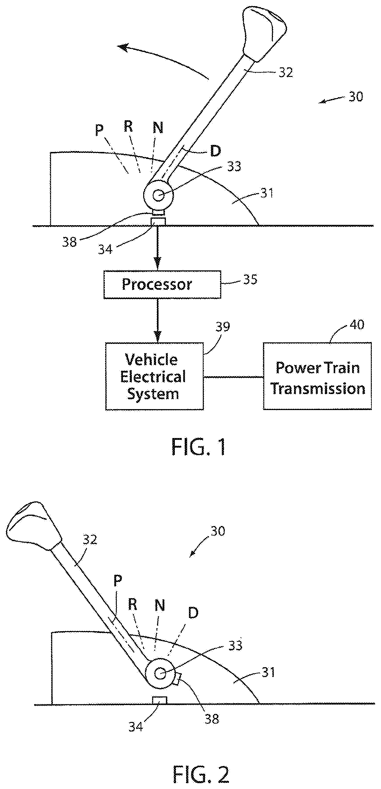
[0016]FIGS. 1 and 2 show a transmission shifter apparatus 30 that includes a base 31,...


PUM


Abstract

An apparatus and method of transmission control includes a shift lever supported between gear positions P, R, N, D, and a sensor operably connected to a vehicle electrical system for generating a variable signal corresponding to the P, R, N, D gear positions. The electrical system is initially set to control shifting a transmission between P, R, N, and D gear positions based on initial P and D position-indicating signals and interpolated/proportional R and N position-indicated signals. The apparatus and method further include adjusting shifting control for improved shift location accuracy after worn shifter components have mechanically worn or electrically drifted, by determining “new” P and D gear positions when the shift lever is in component-worn P and D gear positions, respectively, and then calculating new R and N position-indicating signals.

Description

CROSS-REFERENCE TO RELATED APPLICATION[0001]This application claims priority under 35 U.S.C. § 119(e) upon U.S. Provisional Patent Application No. 62 / 492,351, entitled “TRANSMISSION SHIFTER WITH TRAINED GEAR POSITION SET POINTS” filed on May 1, 2017, by Kirk Ypma et al., the entire disclosure of which is incorporated herein by reference.FIELD OF THE INVENTION[0002]The present invention relates to transmission shifters such as are used in passenger vehicles, and more particularly relates to a shift-by-wire transmission shifter with gear position set points (i.e., “home” positions).BACKGROUND OF THE INVENTION[0003]Transmission shifters for vehicles commonly use a shift lever with positions for selecting different gear positions, such as Park, Reverse, Neutral, and Drive gear positions. When electrical components are used to sense the lever position, these shifters are often called “shift by wire” transmission shifters. Currently many shift-by-wire products use a magnet and a magnetic ...

Claims


Application Information

Patent Timeline
Patent Type & Authority Applications(United States)
IPC IPC(8): F16H61/12F16H59/68F16H59/10F16H61/28
CPCF16H59/68F16H61/12F16H2061/1284F16H2061/1208F16H2342/02F16H61/2807F16H59/105F16H2061/283B60K20/02B60Y2304/09F16H2061/0087B60Y2400/301F16H51/00F16H61/0204
Inventor YPMA, KIRKOLSON, THOMAS
Owner GHSP
Why Eureka
Try Eureka