System and method for tracing polygons in design files

Active Publication Date: 2020-12-10
MAPPEDIN
View PDF3 Cites 0 Cited by
  • Summary
  • Abstract
  • Description
  • Claims
  • Application Information

AI Technical Summary

Benefits of technology

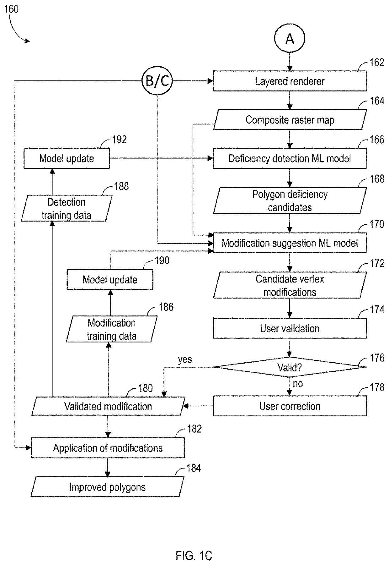
The patent describes a method for extracting polygons from a source file and improving them through machine learning. The method involves filtering the source file to create a planar representation of the vector imagery, dilating the lines to create simplified polygons, and identifying contracted polygons. The method can also include detecting colinear edges, grouping them into sets, and suggesting modifications to improve the polygons. The system can also store the planar representation, the source file, and the modifications for future reference. The technical effect of this patent is to provide a more efficient and accurate method for extracting and improving polygons in source files.

Problems solved by technology

However, in some cases, a design file may not include polygon attributes defining the boundary of the object(s).
This can be done manually, which is time consuming and introduces human error and observer bias.
In other cases, a design file may be “noisy,” with incomplete polygon tracing.
Automated methods of tracing and generating polygons from lines have limitations.
Morphological image processing (i.e. erosion) is computationally intensive.
Further, the existing methods do not integrate user input with machine learning to provide error checking and optimization of polygon tracing and generation.

Method used


Image

  • System and method for tracing polygons in design files
  • System and method for tracing polygons in design files
  • System and method for tracing polygons in design files

Examples


Embodiment Construction

[0042]Various apparatuses or processes will be described below to provide an example of each claimed embodiment. No embodiment described below limits any claimed embodiment and any claimed embodiment may cover processes or apparatuses that differ from those described below. The claimed embodiments are not limited to apparatuses or processes having all of the features of any one apparatus or process described below or to features common to multiple or all of the apparatuses described below.

[0043]One or more systems described herein may be implemented in computer programs executing on programmable computers, each comprising at least one processor, a data storage system (including volatile and non-volatile memory and / or storage elements), at least one input device, and at least one output device. For example, and without limitation, the programmable computer may be a programmable logic unit, a mainframe computer, server, and personal computer, cloud-based program or system.

[0044]Each p...


PUM


Abstract

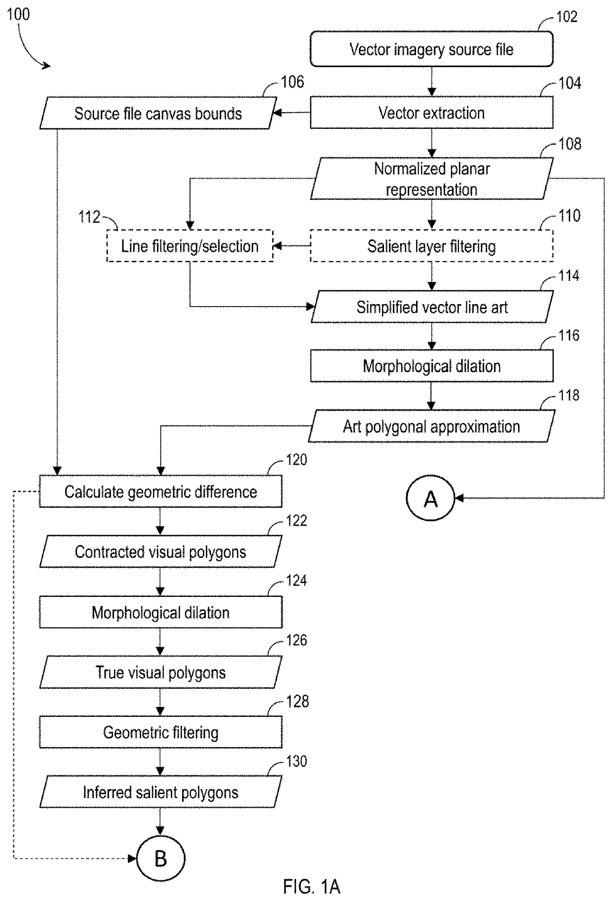
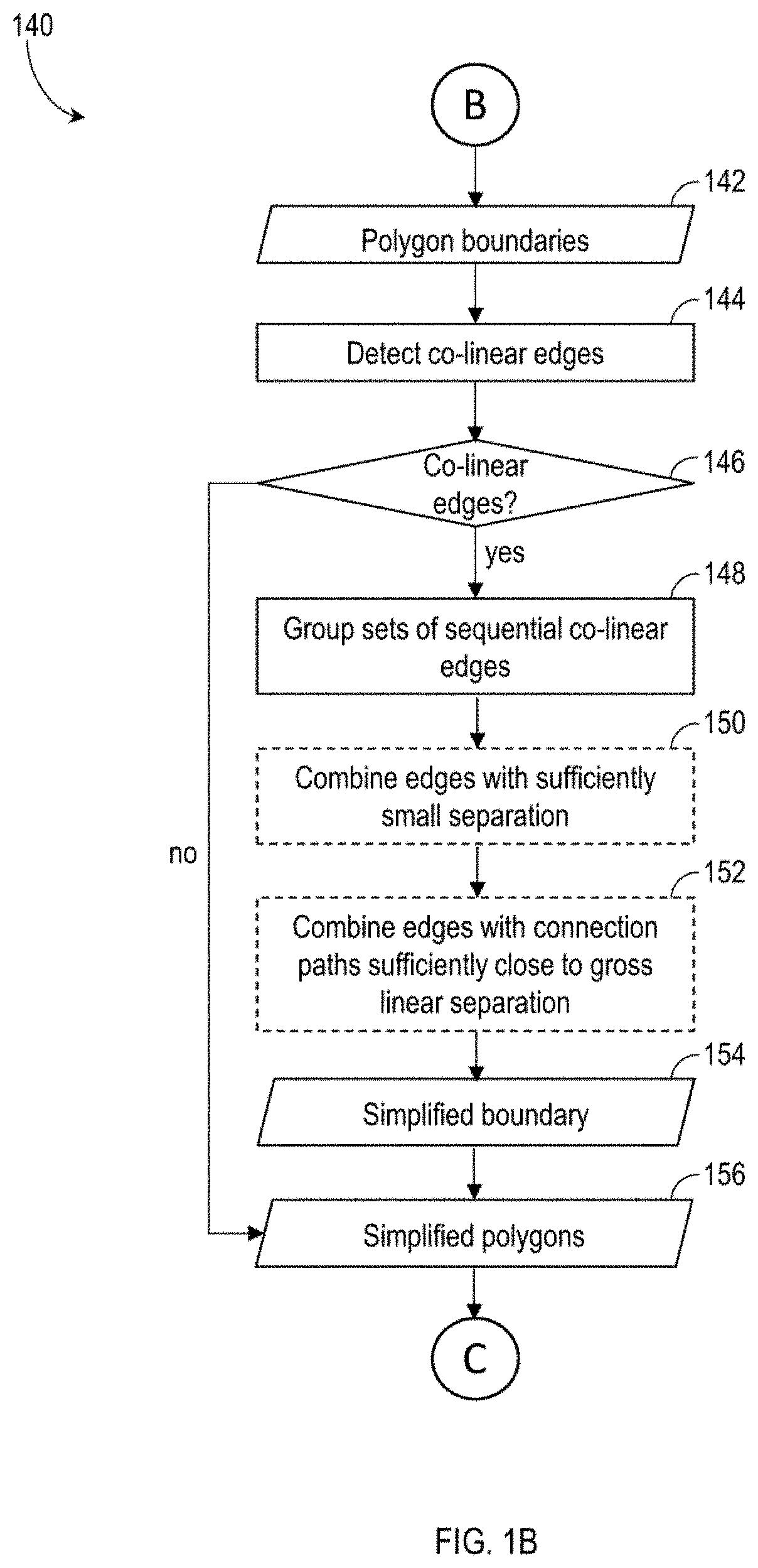
A system and method for tracing polygons in a drawing source file. The method includes extracting vector imagery from the source file, creating a planar representation of the vector imagery as a plurality of lines, filtering the plurality of lines to create simplified line art, morphologically dilating the simplified line art to generate a polygonal approximation, calculating geometric difference between the source file canvas bounds and the polygonal approximation to identify contracted polygons, morphologically dilating the contracted polygons to create visual polygons, and filtering the visual polygons according to one or more geometric parameters to identify salient polygons.

Description

TECHNICAL FIELD[0001]The embodiments disclosed herein relate to automated methods of editing design files, and, in particular to a system and method for tracing polygons in design files containing only line segments.INTRODUCTION[0002]Design files (e.g. CAD, SVG, DXF) are used to create, draft, edit, modify and optimize the design of buildings, machines, electronics, vehicles and other 3D objects in a number of industries. Design files are also used in computer animation for creating advertisement and marketing materials, and for creating artistic works and entertainment media.[0003]Design files may use vector-based graphics or raster graphics to depict the designed objects. Design files, particularly older files, may be of varying quality. It is desirable for a design file to include polygon attributes, to define the boundary of object(s) depicted in the design file, for easier editing and modification. However, in some cases, a design file may not include polygon attributes definin...

Claims


Application Information

Patent Timeline
IPC IPC(8): G06T11/20G06N20/00G06T7/155G06T11/60
CPCG06T11/203G06F30/10G06N20/00G06T7/155G06T2210/04G06T11/60G06T2207/20081G06N20/20
Inventor HARTFIEL, ADAMWEI, ERKANG
Owner MAPPEDIN
Why Eureka
Try Eureka