
Hair-drying hood and hair treatment device including the same

a hair-drying hood and hair treatment technology, which is applied in the direction of hair cleaning, hair drying, hair equipment, etc., can solve the problems of inconvenient use, inability to meet the requirements of portability, and products that are too bulky and heavy to carry on the road, so as to achieve convenient folding and storage, convenient storage and hand-free operation, and convenient storage

Active Publication Date: 2020-12-17
CHANG STEPHANIE
View PDF0 Cites 0 Cited by
  • Summary
  • Abstract
  • Description
  • Claims
  • Application Information

AI Technical Summary

Benefits of technology

The hair treatment and hair-drying devices described in this patent are designed to provide quick and uniform heating, easy storage and hand-free operation, and to exempt users from uncomfortable feelings. These devices are particularly suitable for use at home or while traveling. They include a conical flow-guiding plate made of foldable cloth, which helps to distribute hot air evenly and direct it towards the air outlet, resulting in efficient heating and a gentle blow for the hair. Additionally, the air flow passage structure is easy to store and can be quickly folded onto itself for easy transport and storage.

Problems solved by technology

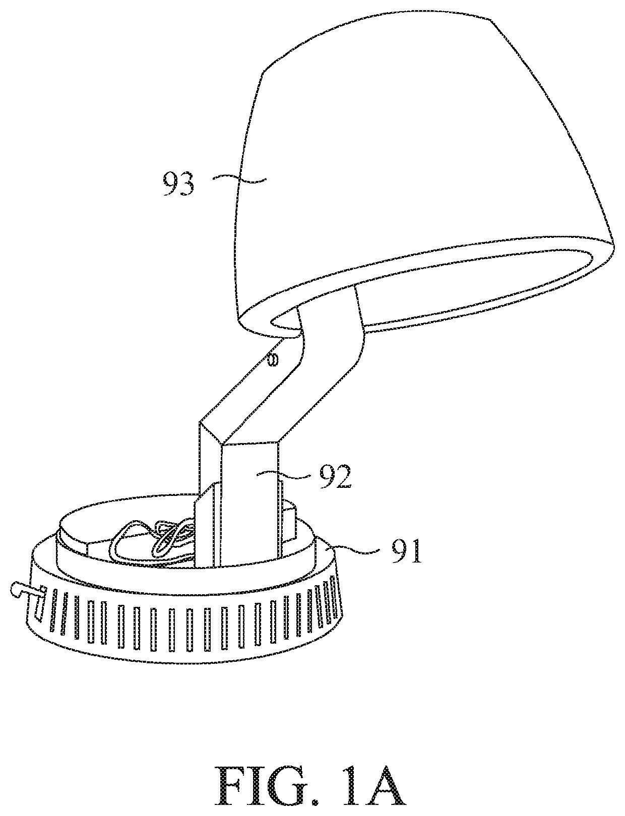
A hair dryer needs a user to hold it with his hand, and it is necessary to change positions frequently to make the hair evenly exposed to wind and heat, which will cause inconvenience to the user.
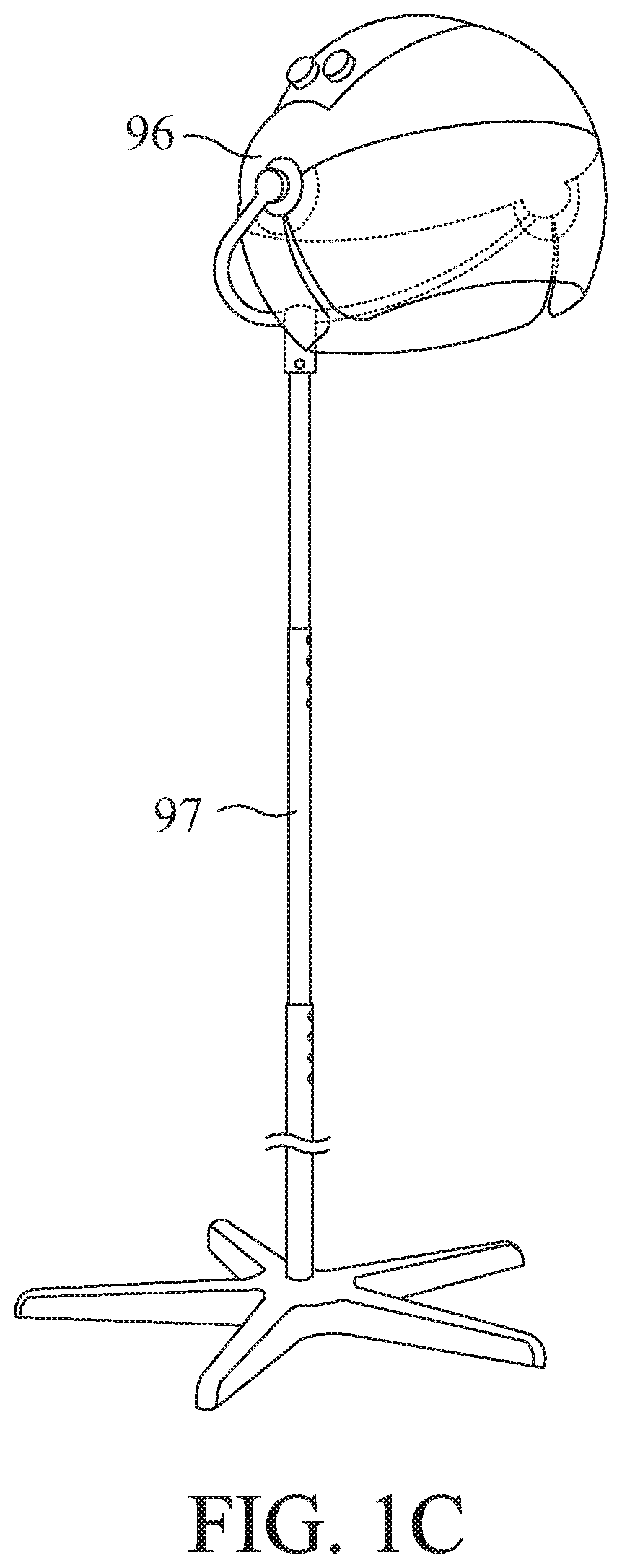
Disadvantageously, such products are too bulky and heavy to be carried for traveling.
Even if the bracket 92 can be folded so that the base 91 and the head hood 93 can be combined, it is still difficult to achieve the requirements for portability.
Moreover, the transmission path between the blower module in the base 91 and the head hood 93 is too long to be efficient for drying, and too much energy consumption is caused.
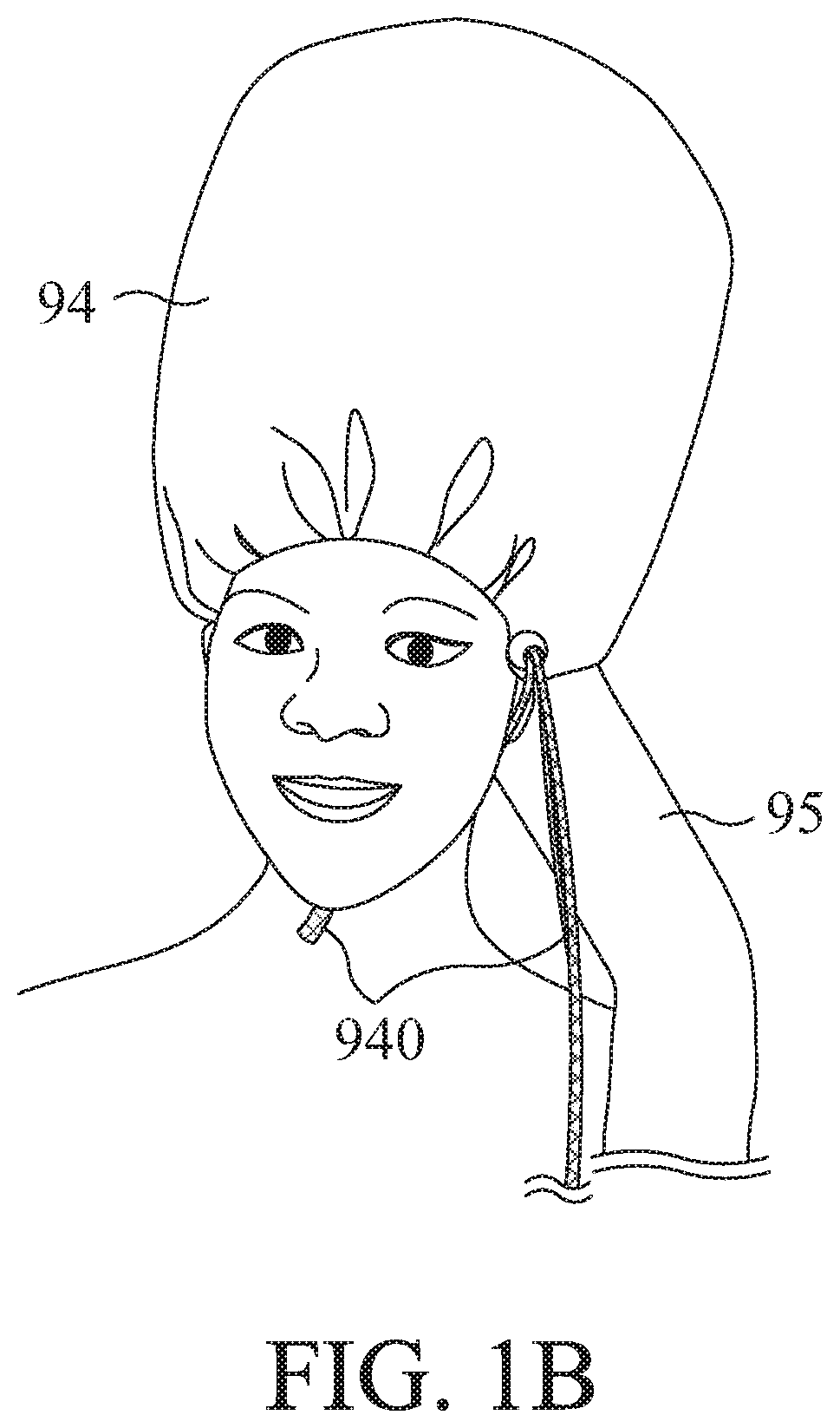
However, as can be seen from the figure, the hot air flow entering the hair hood 94 and temporarily staying therein will cause the internal air pressure to rise.
As a result, it is not easy for the hair hood 94 to remain on the user's head.

Method used


Image

  • Hair-drying hood and hair treatment device including the same
  • Hair-drying hood and hair treatment device including the same
  • Hair-drying hood and hair treatment device including the same

Examples


Embodiment Construction

[0041]Please refer to FIG. 2A, which is a schematic diagram illustrating the structure of a hair-drying hood of a hair treatment device, which includes a hair dryer hood 11 for covering a user's head. Therefore, the hair-drying hood 11 is substantially designed to match the contour of a user's head, but is not limited to a particular shape. Depending on designs, the top view of the hair-drying hood 11 may be circular, elliptical, etc., and the cross-sectional view may be trapezoidal, rectangular or semi-circular.

[0042]For illustration purposes, the present embodiment is exemplified under a configuration with a circular top-view shape and a trapezoidal cross-sectional shape. A top portion of the hair-drying hood 11 is provided with an opening 110 for allowing a blower (not shown) or other hot air supply tube to be inserted. An elastic strap 12 is wrapped around the edge of the opening 110 for fixedly combining the air outlet of the blower, and the hair-drying hood 11, and is adapted ...


PUM


Abstract

A hair treatment device can be used with a blower for drying and styling hair. The hair treatment device includes a hair-drying hood for covering the head of a user, which has an opening at a top portion or a side portion thereof. The blower can be inserted from the opening. The hair-drying hood further includes an outer layer, where the opening is disposed, and a thermal layer, which forms an air flow guiding chamber together with the outer layer inbetween for introducing and dispersing hot air from the blower all over the hair-drying hood while raising a temperature of the thermal layer. The hair treatment device further includes a position retainer having a first end fixing the blower, and having a second end is stably fixed onto an object.

Description

FIELD OF THE INVENTION[0001]The present invention relates to a hair-drying hood and a hair treatment device including a hair-drying hood, and more particularly to a hair-drying hood and a hair treatment device including a hair-drying hood for use with a blower.BACKGROUND OF THE INVENTION[0002]Hair style is an important part of fashion, so people need to take care of it from time to time. The most common thing to do is to use a hair dryer to evaporate water in the hair. A hair dryer needs a user to hold it with his hand, and it is necessary to change positions frequently to make the hair evenly exposed to wind and heat, which will cause inconvenience to the user. To improve such disadvantages, a variety of hair-drying devices have been developed.[0003]Please refer to FIG. 1A, which is a schematic view showing the appearance of a conventional household hair drying device. A base 91 is provided with a blower module (not shown) for generating a hot air flow, which is delivered to a hair...

Claims


Application Information

Patent Timeline
IPC IPC(8): A45D20/14A45D20/18A45D20/22
CPCA45D20/18A45D2200/205A45D20/22A45D20/14
Inventor CHANG, STEPHANIE
Owner CHANG STEPHANIE
Learn More