
Gas turbine blade and method for producing such blade

a technology of gas turbine blades and blades, applied in the direction of blade accessories, machine/engines, engine fuctions, etc., can solve the problem of low solidity

Active Publication Date: 2020-12-17
SIEMENS ENERGY GLOBAL GMBH & CO KG
View PDF0 Cites 3 Cited by
  • Summary
  • Abstract
  • Description
  • Claims
  • Application Information

AI Technical Summary

Benefits of technology

The present invention provides a gas turbine blade design that allows for higher power output, efficiency, and economic attractiveness of gas turbine engines. The blade design is based on its solidity ratio, which measures the efficiency of the blade as a structure. The ideal blade design would have a thin tip and a large chord length for good performance. The invention also provides a method for producing the gas turbine blade by casting a hollow airfoil and machining the external surface of the airfoil in a specific zone to reduce the wall thickness of the main wall and / or the trailing edge thickness in the zone.

Problems solved by technology

This is because a large amount of metal is required to support the pull load of the upper sections and only a small core passage is required to pass a sufficient amount of cooling air to mitigate creep failure.
High solidity near the hub is not a challenge from manufacturing perspective, but low solidity near the tip is a challenge due to the aforementioned wall thickness requirements during casting.

Method used


Image

  • Gas turbine blade and method for producing such blade
  • Gas turbine blade and method for producing such blade
  • Gas turbine blade and method for producing such blade

Examples


Embodiment Construction

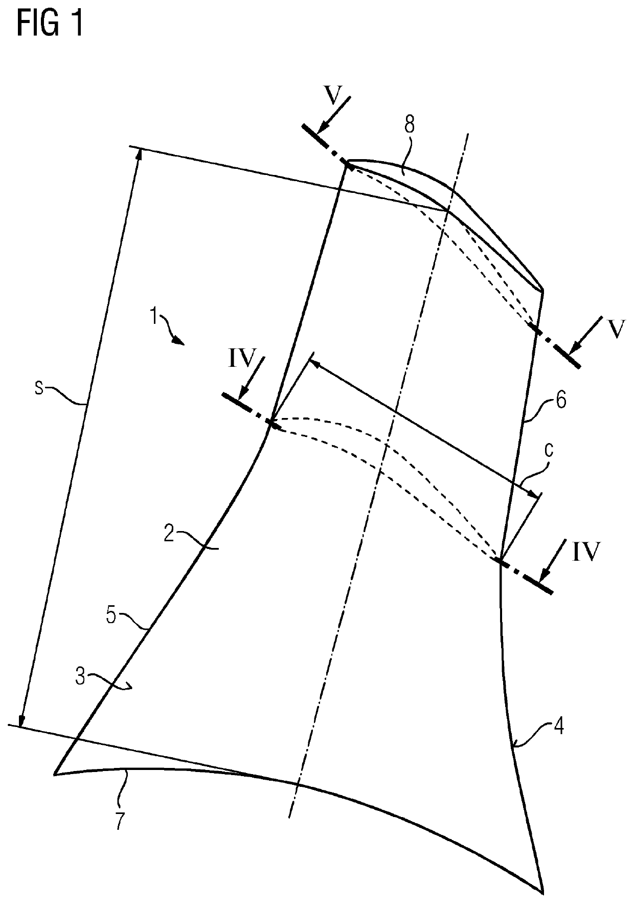
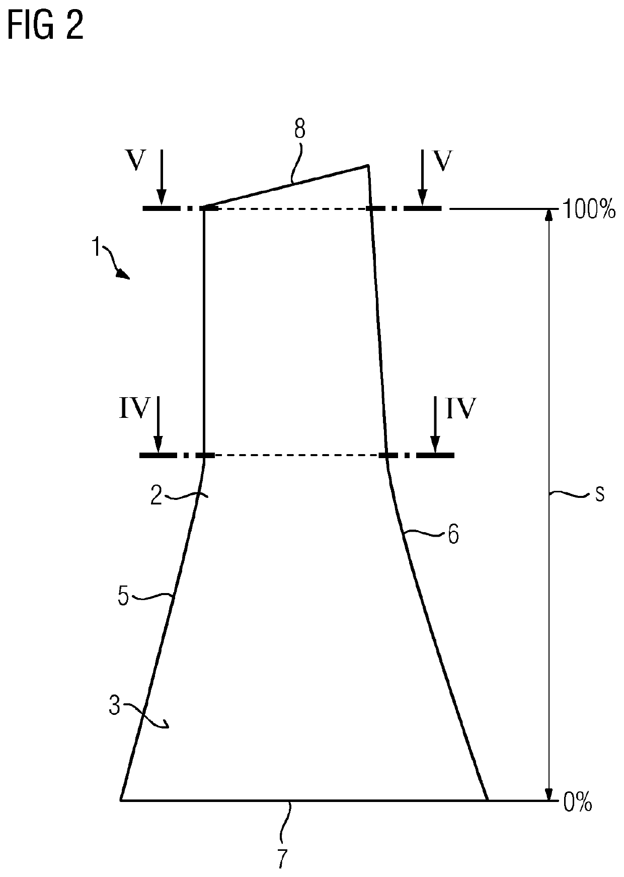
[0039]FIGS. 1 and 2 show different views of a gas turbine blade 1 according to an embodiment of the present invention. The gas turbine blade 1 comprises a metal airfoil 2 with a main wall having a first side wall 3 and a second side wall 4, which are coupled to each other at a leading edge 5 and a trailing edge 6. The airfoil 2 extends in a radial direction from a blade root 7 to a blade tip 8, defines a radial span s from 0% at the blade root 7 to 100% at the blade tip 8, has a radial span dependent chord length c defined by a straight line connecting the leading edge 5 and the trailing edge 6, and has a radial span dependent solidity ratio rs of metal area to total cross-sectional area. Moreover, the main wall defines three interior cavities 9, which are separated from each other by partition walls 10 each extending between the first side wall 3 and the second side wall 4.

[0040]The gas turbine blade 1 is a casted product, whereas the external surface of the main wall of the casted...


PUM


Abstract

A gas turbine blade having a casted metal airfoil, the airfoil has a main wall defining at least one interior cavity, having a first side wall and a second side wall, which are coupled to each other at a leading edge and a trailing edge, extending in a radial direction from a blade root to a blade tip and defining a radial span from 0% at the blade root to 100% at the blade tip. The main airfoil has a radial span dependent chord length defined by a straight line connecting the leading edge and the trailing edge as well as a radial span dependent solidity ratio of metal area to total cross-sectional area. Solidity ratios in a machined zone of the airfoil from 80% to 85% of span are below 35%, in particular all solidity ratios in the zone.

Description

CROSS REFERENCE TO RELATED APPLICATIONS[0001]This application is the US National Stage of International Application No. PCT / US2019 / 012672 filed 8 Jan. 2019, and claims the benefit thereof. The International Application claims the benefit of European Application No. EP18151215 filed 11 Jan. 2018. All of the applications are incorporated by reference herein in their entirety.FIELD OF INVENTION[0002]The present invention relates to a gas turbine blade having a casted metal airfoil, said airfoil comprising a main wall defining at least one interior cavity, having a first side wall and a second side wall, which are coupled to each other at a leading edge and a trailing edge, extending in a radial direction from a blade root to a blade tip and defining a radial span from 0% at the blade root to 100% at the blade tip, wherein said airfoil has a radial span dependent chord length defined by a straight line connecting the leading edge and the trailing edge as well as a radial span dependent ...

Claims


Application Information

Patent Timeline
Patent Type & Authority Applications(United States)
IPC IPC(8): F01D5/18F01D5/14
CPCF05D2240/304F05D2230/21F01D5/147F05D2260/20F05D2240/301F01D5/18F01D5/187F05D2260/941F05D2230/10
Inventor ESHAK, DANIEL M.KAMENZKY, SUSANNELOHAUS, ANDREWVÖHRINGER, DANIELMILLER, JR., SAMUEL R.
Owner SIEMENS ENERGY GLOBAL GMBH & CO KG
Learn More