Control method for vehicle air conditioning, and vehicle air conditioning device
- Summary
- Abstract
- Description
- Claims
- Application Information
AI Technical Summary
Benefits of technology
Problems solved by technology
Method used
Image
Examples
first embodiment
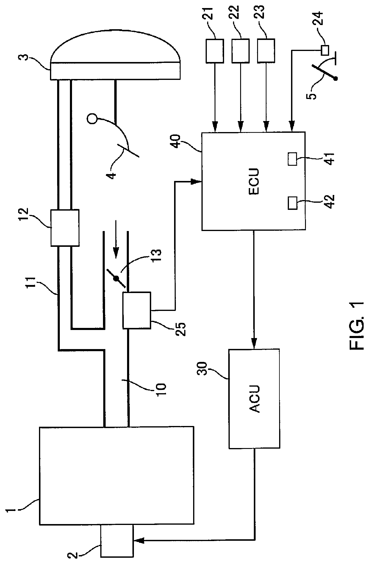
[0012]FIG. 1 is a system diagram of a vehicle to which an air-conditioning device for a vehicle of the first embodiment is applied. An engine 1, which is an internal combustion engine, takes in air from an intake manifold 10. The intake manifold 10 is provided with a throttle valve 13, and an amount of air taken in is controlled in accordance with a position of an acceleration pedal 5 operated by a driver. On the intake manifold 10, between the throttle valve 13 and the engine 1, a negative pressure supply passage 11 is connected and an intake pressure sensor 25 is provided. The intake pressure sensor 25 detects negative pressure inside the intake manifold 10 (written hereinafter as PIM), and outputs the detected pressure to an engine control unit 40 (described hereinafter). The negative pressure supply passage 11 is connected to a vacuum servo 3.
[0013]The vacuum servo 3 is a negative pressure booster that assists stepping force applied to a brake pedal 4 by introducing negative pre...
PUM
 Abstract
Description
Claims
Application Information
 - R&D
- Intellectual Property
- Life Sciences
- Materials
- Tech Scout
- Unparalleled Data Quality
- Higher Quality Content
- 60% Fewer Hallucinations
Browse by: Latest US Patents, China's latest patents, Technical Efficacy Thesaurus, Application Domain, Technology Topic, Popular Technical Reports.
© 2025 PatSnap. All rights reserved.Legal|Privacy policy|Modern Slavery Act Transparency Statement|Sitemap|About US| Contact US: help@patsnap.com


