
Display panel, display module and electronic device

a technology of display panel and display module, applied in the field of display technology, can solve problems affecting and achieve the effect of improving the display effect of the display panel and improving the quality of the display panel

Inactive Publication Date: 2020-12-24
WUHAN CHINA STAR OPTOELECTRONICS TECH CO LTD
View PDF0 Cites 0 Cited by
  • Summary
  • Abstract
  • Description
  • Claims
  • Application Information

AI Technical Summary

Benefits of technology

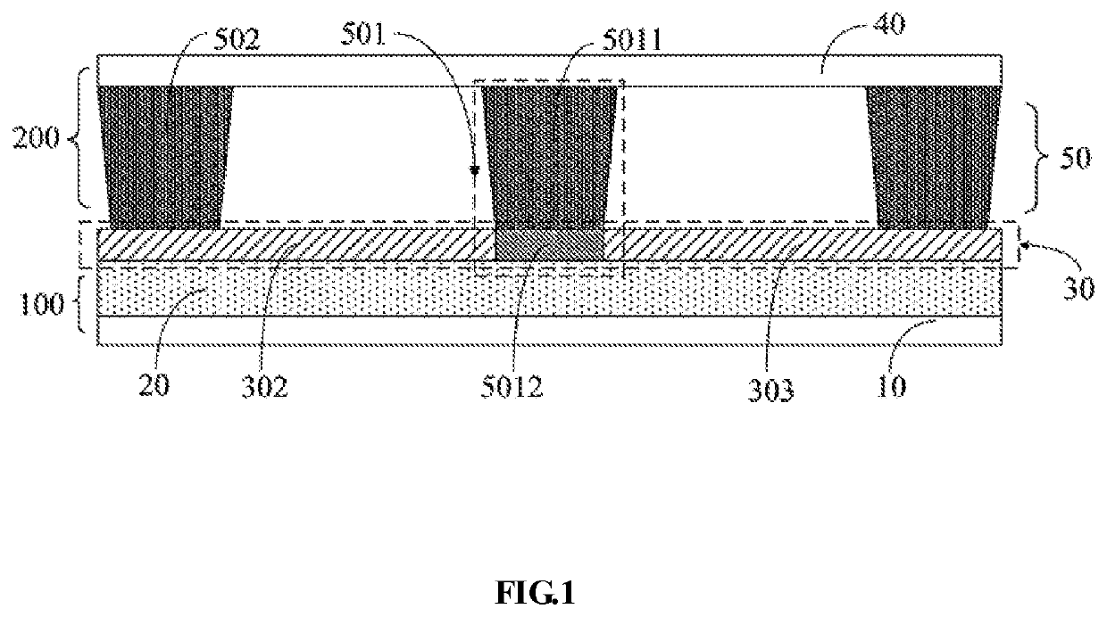
The present invention provides a display panel that solves the problem of unevenly displaying by using spacers with different heights to eliminate gaps between the spacers and color filter substrate. This improves the display effect and quality of the display panel.

Problems solved by technology

Therefore, a part of the spacers will be disposed in the recesses, resulting in a certain gap between the spacers and the color filter substrate, so that partial regions of the display panel are unevenly displayed, which affects the quality of the display panel.

Method used


Image

  • Display panel, display module and electronic device
  • Display panel, display module and electronic device
  • Display panel, display module and electronic device

Examples


second embodiment

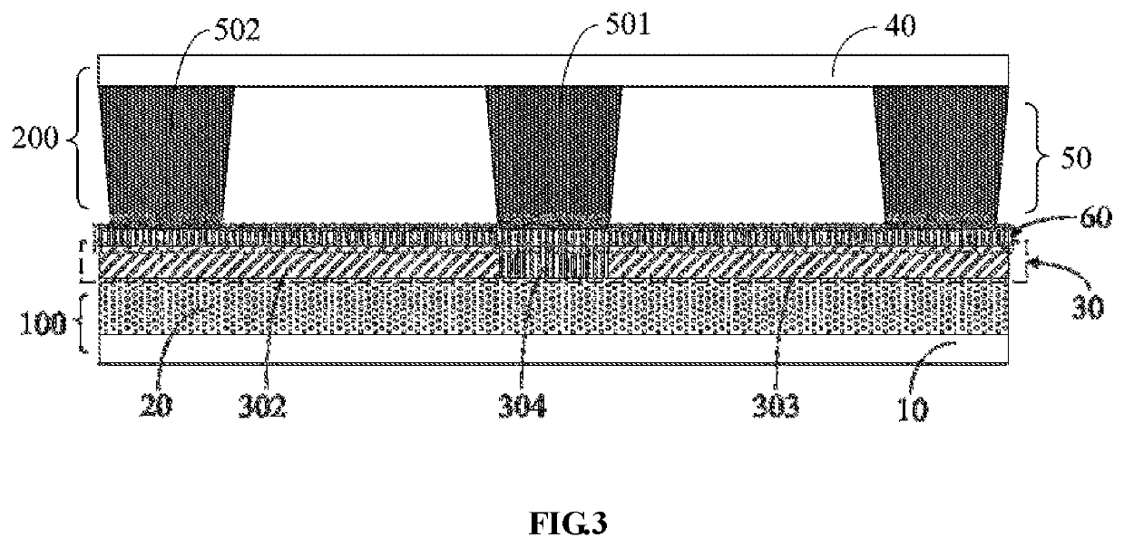
[0074]Referring to FIG. 3, FIG. 3 is a schematic layer view of a display panel according to the present invention.

[0075]The display panel further includes a protection layer 60 disposed on the first common electrode plate 302. The surface of the protection layer 60 away from the first substrate 10 is a flat surface.

[0076]In one embodiment of the present application, the height of the first spacer 501 is the same as the height of the second spacer 502.

[0077]In an embodiment of the present application, the material of the protection layer 60 may be a high fluidity insulating material. When the protection layer 60 is formed, the protection layer 60 fills the recess 304 to ensure that the surface of the protection layer 60 away from the first substrate 10 is a flat surface.

first embodiment

[0078]In one embodiment of the present application, the heights of the first spacer 501 and the second spacer 502 can be set to have the same height without the cumbersome arrangement of the

[0079]Furthermore, another embodiment of the present invention provides display module including a display panel, a touch layer, a polaroid layer and a cover layer. The touch layer, the polaroid layer and the cover layer are disposed on the display panel.

[0080]According to still another aspect of the present application, an electronic device is provided. The electronic device including the display module. The electronic device may be, including but not limited to, a mobile phone, a tablet computer, a computer display, a game machine, a television, a display screen, a wearable device, and other daily appliances or household appliances having a display function.

[0081]The working principle of the display module, the electronic device, and the display panel are similar. The working principle of the d...


PUM

PropertyMeasurementUnit
heightaaaaaaaaaa
widthaaaaaaaaaa
fixed distanceaaaaaaaaaa

Abstract

A display panel, a display module and an electronic device are provided. The display panel includes an array substrate and a color filter. The array substrate includes a first substrate and a first common electrode layer disposed on the first substrate. The color filter substrate is disposed against the array substrate. The color filter substrate includes a second substrate and a spacer on the second substrate. The spacer includes a first spacer and a second spacer. A height of the first spacer is higher than or equal to a height of the second spacer.

Description

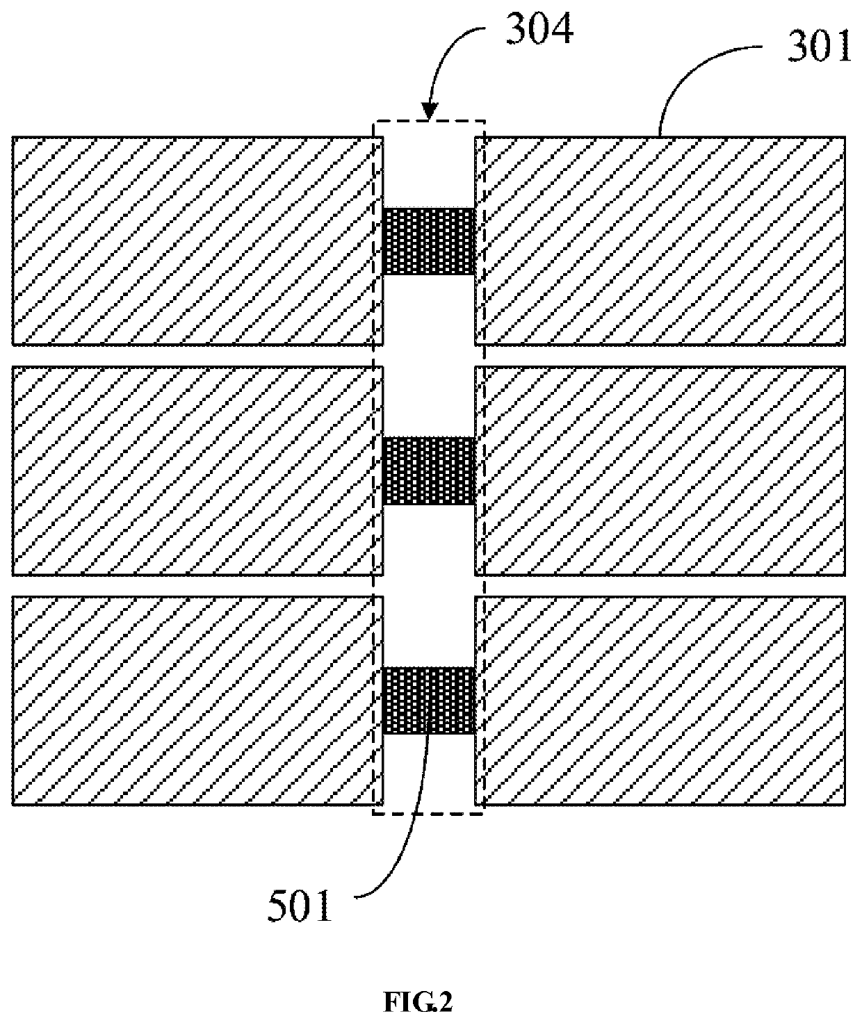
BACKGROUND OF THE INVENTIONField of Invention[0001]The present invention relates to a display technology, and more particularly to a display panel, a display module and an electronic device.Description of Prior Art[0002]In the existing technology, the display panel includes an array substrate, a color filter substrate, and a spacer therebetween. As an important part, the spacer has always been a special consideration in design. The main function of the spacer is to support the upper and lower substrates to maintain a fixed distance between the array substrate and the color filter substrate. The material properties of the spacer itself determine that it has a certain compression ratio, so that the panel can be properly adjusted for small range spacing during handling or pressing.[0003]The array substrate includes a common electrode plate distributed in an array. In the row direction, there are recesses resulted from certain distance between adjacent common electrode plates. Therefore...

Claims


Application Information

Patent Timeline
Patent Type & Authority Applications(United States)
IPC IPC(8): G02F1/1339G06F3/041G02F1/1335G06F1/16
CPCG02F1/13394G06F3/0412G02F1/133514G06F1/1609G02F2001/13396G02F1/13396G06F1/1637G06F2200/1613G02F1/13338G02F1/134318
Inventor GAO, LING
Owner WUHAN CHINA STAR OPTOELECTRONICS TECH CO LTD
Learn More