Anti-ejection apparatus for wafer units

Active Publication Date: 2020-12-24
DISCO CORP
View PDF0 Cites 1 Cited by
  • Summary
  • Abstract
  • Description
  • Claims
  • Application Information

AI Technical Summary

Benefits of technology

[0003]The lock mechanisms disclosed in JP 2013-157381 A and JP 2016-119354 A, however, involve a problem that ch

Problems solved by technology

The lock mechanisms disclosed in JP 2013-157381 A and JP 2016-119354 A, however, involve a problem that chang

Method used


Image

  • Anti-ejection apparatus for wafer units
  • Anti-ejection apparatus for wafer units
  • Anti-ejection apparatus for wafer units

Examples


embodiment

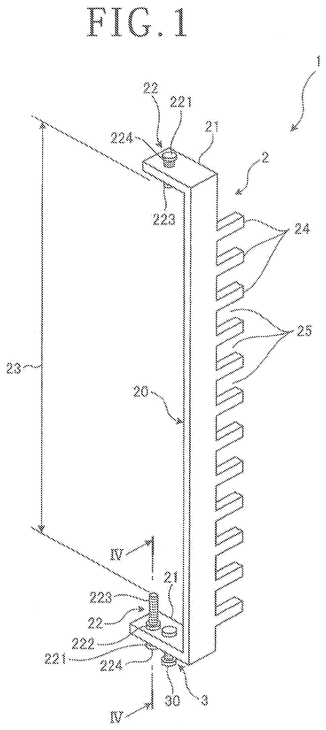
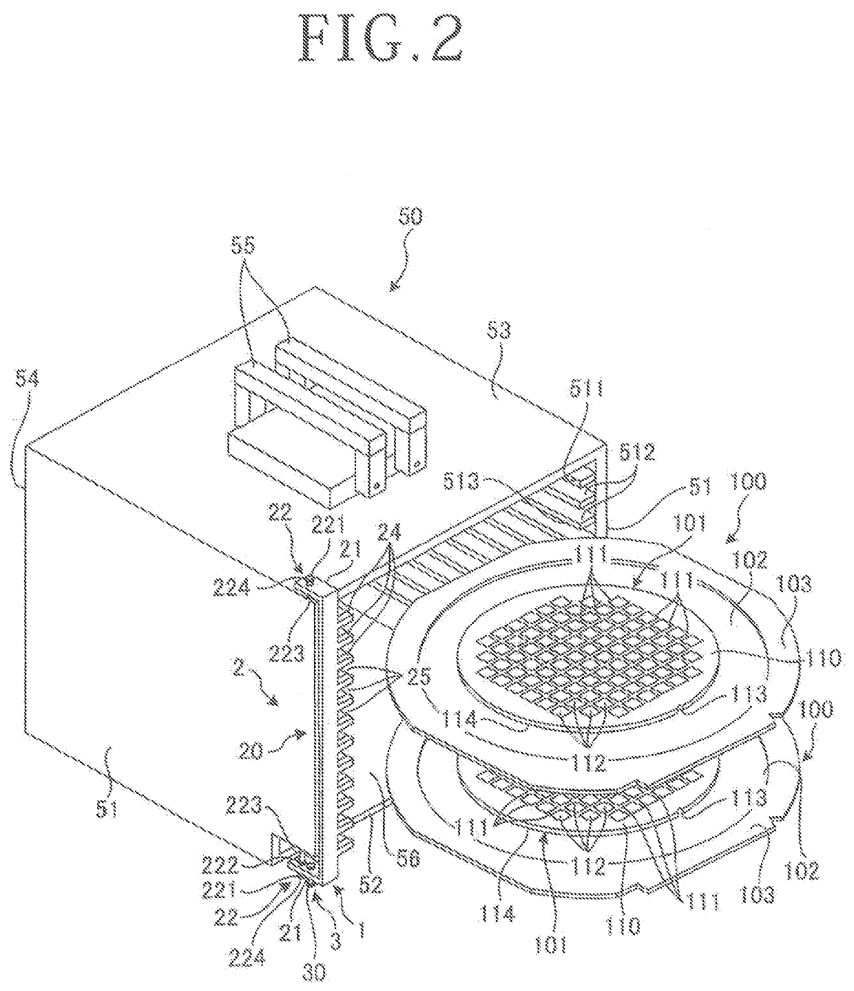
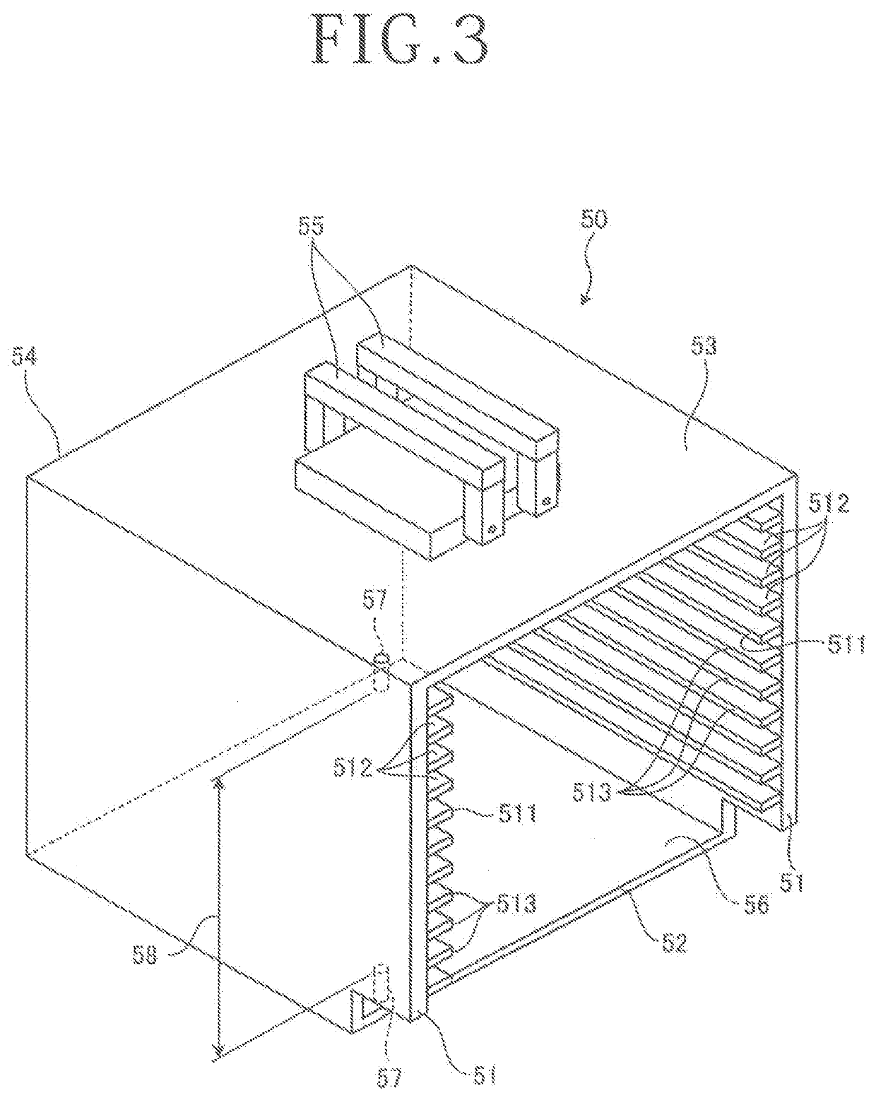
[0019]An anti-ejection apparatus according to the embodiment of the present invention for wafer units will be described based on the relevant figures of the drawings. FIG. 1 is a perspective view depicting a configuration example of an anti-ejection apparatus according to an embodiment for wafer units. FIG. 2 is a perspective view depicting the anti-ejection apparatus of FIG. 1 together with a cassette to which the anti-ejection apparatus is attached. FIG. 3 is a perspective view of the cassette depicted in FIG. 2. FIG. 4 is a cross-sectional view taken along line IV-IV in FIG. 1.

[0020]The anti-ejection apparatus of FIG. 1 according to the embodiment for the wafer units (hereinafter simply referred to as “the anti-ejection apparatus”) is used in attachment to a cassette 50 as depicted in FIG. 2. The cassette 50 is a container that as depicted in FIG. 2, can contain a plurality of wafer units 100 of ring-shaped frames 103 and wafers 101 integrated together via adhesive tapes 102, res...

first modification

[0047]An anti-ejection apparatus according to a first modification of the embodiment of the present invention for wafer units will be described based on the relevant figure of the drawings. FIG. 9 is a cross-sectional view of a lower bar mounting fixture of the anti-ejection apparatus according to the first modification of the embodiment for wafer units. In FIG. 9, like elements as in the embodiment are identified by like reference numerals, and their description is omitted herein.

[0048]The anti-ejection apparatus 1-1 according to the first modification for the wafer units (hereinafter simply referred to as “the anti-ejection apparatus”) has the same configuration as the anti-ejection apparatus 1 according to the embodiment except for a difference in the configuration of the bar attachment fixtures 22 that the recesses 57 are not included. As depicted in FIG. 9, a lower bar attachment fixture 22-1 of the anti-ejection apparatus 1-1 is fixedly secured between the lower surface of the...

second modification

[0050]An anti-ejection apparatus according to a second modification of the embodiment of the present invention for wafer units will be described based on the relevant figure of the drawings. FIG. 10 is a cross-sectional view of a guide pin of the anti-ejection apparatus according to the second modification of the embodiment for the wafer units. In FIG. 10, like elements as in the embodiment are identified by like reference numerals, and their description is omitted herein.

[0051]The anti-ejection apparatus 1-2 according to the second modification for the wafer units (hereinafter simply referred to as “the anti-ejection apparatus”) has the same configuration as the anti-ejection apparatus 1 according to the embodiment except for a difference in the configuration for attachment of a guide pin 3-2 to the lower attachment part 21. As depicted in FIG. 10, the guide pin 3-2 of the anti-ejection apparatus 1-2 includes a cylindrical threaded portion 31 with a thread formed on an outer periph...


PUM


Abstract

An anti-ejection apparatus for wafer units includes a lock bar and a guide pin. The lock bar alternately has a plurality of lock portions and a plurality of unlock portions. The lock portions are located at heights corresponding to those of insertion slots of a side plate of a cassette, and enable blocking of the insertion slots. The unlock portions enable unblocking of the insertion slots. The guide pin is connected to the lock bar and is disposed protruding downward from a bottom portion of the side plate of the cassette. When the guide pin is pressed upward at its lower end portion, the unlock portions and the insertion slots are communicated with each other. When the pressing of the lower end portion of the guide pin is cancelled, on the other hand, the insertion slots are blocked by lock portions.

Description

BACKGROUND OF THE INVENTIONField of the Invention[0001]The present invention relates to an anti-ejection apparatus for wafer units.Description of the Related Art[0002]To divide a semiconductor wafer into chips, a cutting machine called a dicing saw is used. As a preparation for processing wafers by a cutting machine of this type, the wafers are each fixed on a ring-shaped frame via an adhesive tape and are contained in a cassette. The cassette with the wafers contained therein is transferred by an operator to the cutting machine, and is mounted on a cassette mounting table disposed on the cutting machine. The wafers are sequentially carried out from the cassette, subjected to dicing processing, and then carried back into the cassette. The cassette with the diced wafers contained therein is again transferred by the operator to a machine that performs the next step. To prevent accidental ejection of wafers from such a cassette during its transfer, various cassettes provided with diffe...

Claims


Application Information

Patent Timeline
IPC IPC(8): H01L21/673
CPCH01L21/67383H01L21/67373H01L21/67309H01L21/67386H01L21/6732H01L21/67092H01L21/67132H01L21/6836H01L2221/68327
Inventor SOEJIMA, YOSHIKATSU
Owner DISCO CORP
Why Eureka
Try Eureka