
Louver assembly

a technology of louver and assembly, which is applied in the direction of lighting and heating apparatus, heating types, ventilation systems, etc., can solve the problems of affecting the performance of louver assemblies, affecting the drainage of rainwater, and affecting the design of louver

Pending Publication Date: 2021-01-07
MESTEK
View PDF6 Cites 2 Cited by
  • Summary
  • Abstract
  • Description
  • Claims
  • Application Information

AI Technical Summary

Benefits of technology

The present invention is a louver assembly that allows air to flow through while also allowing water to drain out. This is particularly useful in situations where there is a lot of water accumulation and wind is blowing. The louver assembly is designed to meet the stringent requirements of the Florida Building Code and Miami-Dade County Building Code, including high volume flow rate, impact resistance, water penetration protection, and high wind-loads. The louver assembly includes a blade stack and a windbreak that helps divert wind away from the front of the louver assembly, allowing water to drain out of it.

Problems solved by technology

Recent natural disasters and code modifications have placed larger burdens on the performance of louver assemblies that are integrated into various ventilation systems.
Buildings in areas of the world that are especially prone to hurricanes, however, face much tougher problems with the design of louvers.
Sustained, direct, positive airflow due to wind at the front face of the louver, however, may inhibit draining of the captured rainwater, and in some situations may actually push accumulated water through the lover and into the building.

Method used


Image

  • Louver assembly
  • Louver assembly
  • Louver assembly

Examples


Embodiment Construction

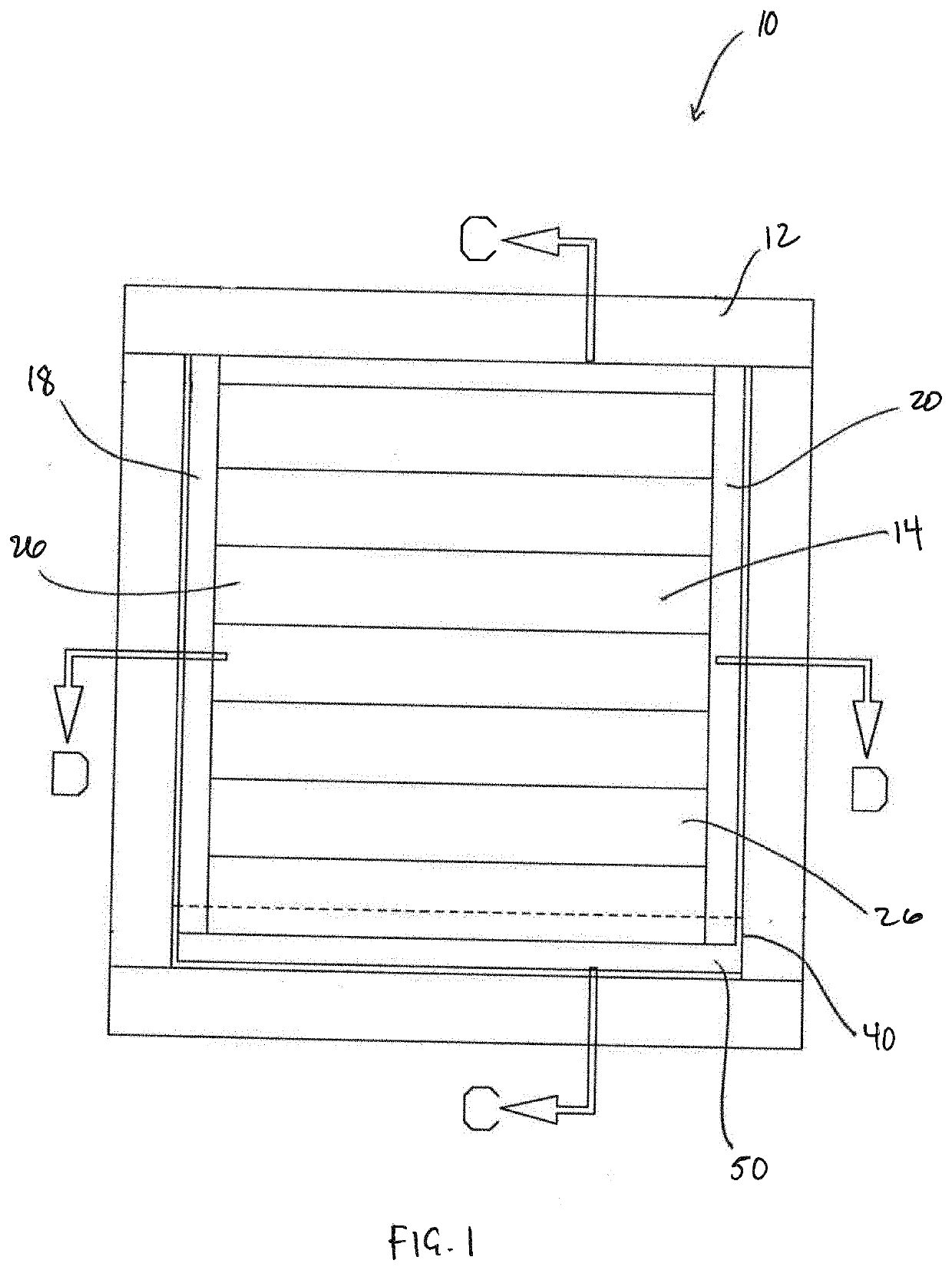
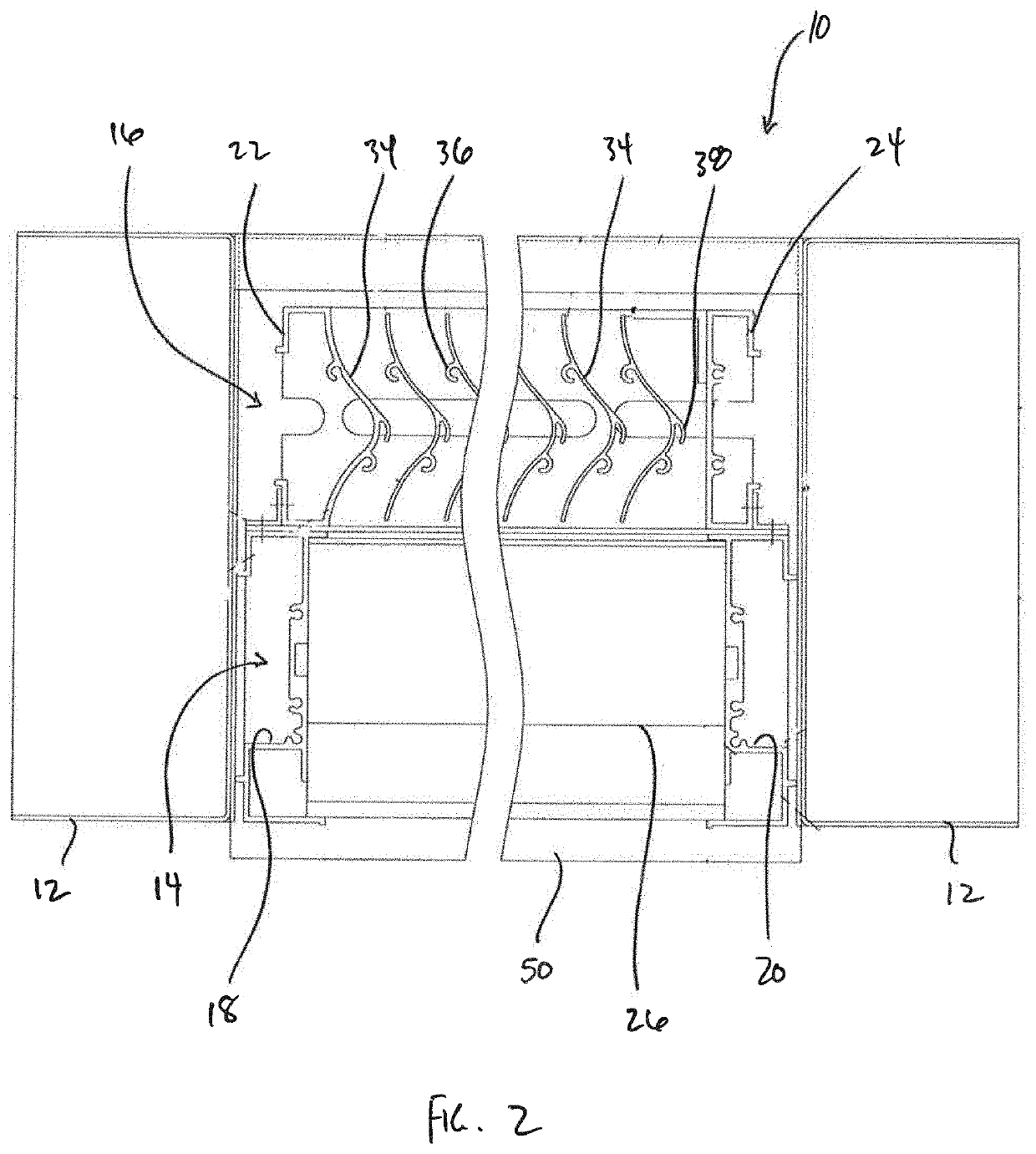
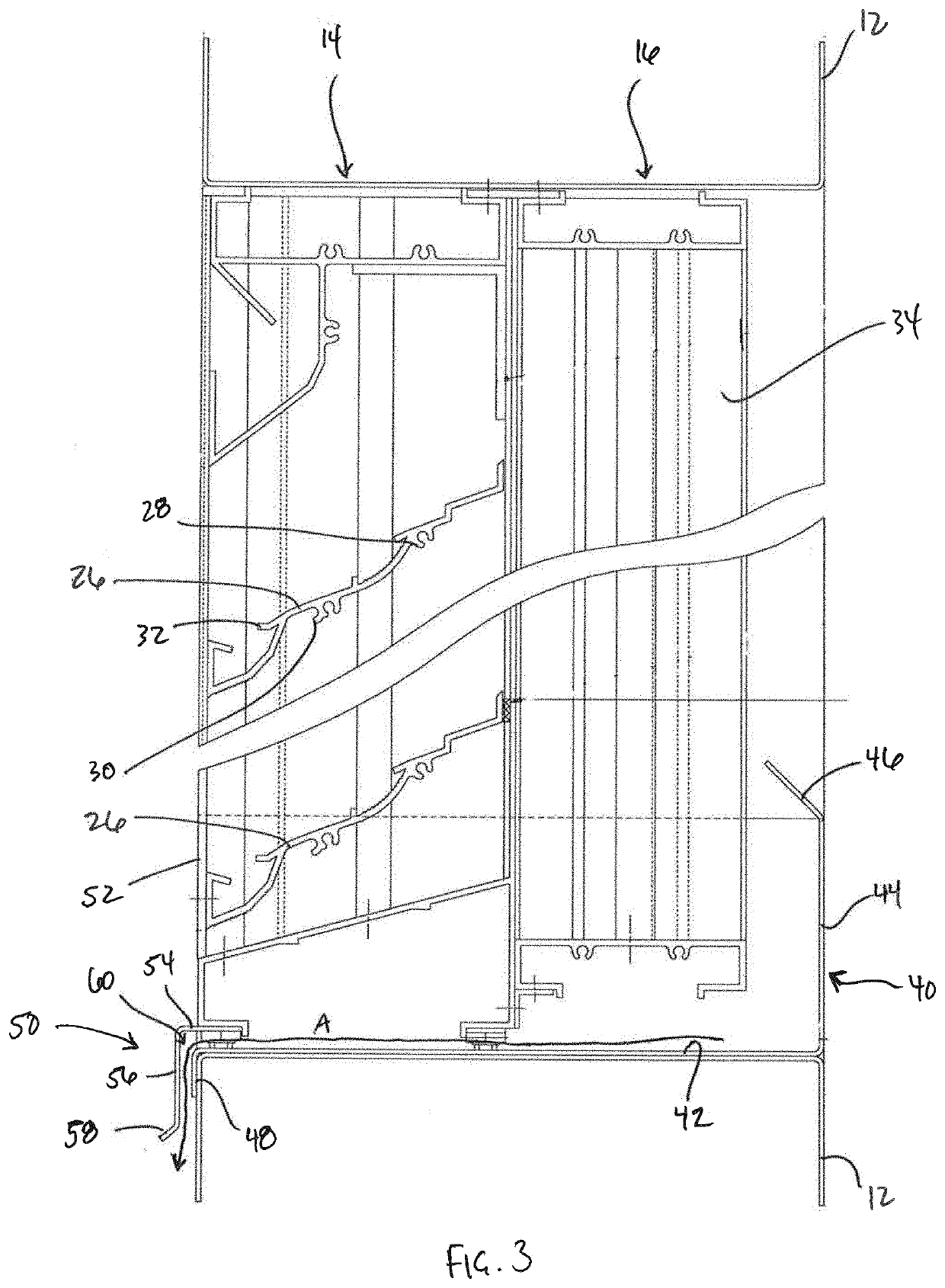
[0020]With reference to FIGS. 1-3, a louver assembly 10 according to an embodiment of the invention is illustrated. The lover assembly 10 is designed to be inserted within an opening in a wall of a building to permit outside air to flow therethrough into the building while removing water particles from the air to prevent excess moisture from entering the building. While the louver assembly 10 is disclosed herein as being disposed within an opening in a wall of a building or other structure, it will be readily appreciated, however, that the louver assembly 10 may be integrated into any known ventilation system, including those systems having stand-alone components, without departing from the broader aspects of the present invention.

[0021]As illustrated in FIGS. 1-3, the louver assembly 10 includes a generally rectangular outer frame 12 formed from generally U-shaped sleeves (including, for example, top, bottom, left and right sleeves). The sleeves, and thus the frame 12, may be forme...


PUM


Abstract

A louver assembly for placement in an opening for regulating the inlet of air includes a first blade stack having a plurality of elongated blades mounted within a frame having an upper frame member and a lower frame member, the lower frame member defining a sill, and a windbreak positioned adjacent to a front face of the louver assembly and extending from a point above the sill to a point below the sill. The windbreak is configured to divert wind at the front face of the louver assembly above the sill to facilitate draining of water from the louver assembly.

Description

FIELD OF THE INVENTION[0001]The present invention relates generally to louver assemblies that helps regulate the inlet of outside ambient air and, more particularly, to a louver assembly which inhibits air-born particulates such as rain droplets that are entrained in the ambient air from passing through the lover assembly and into the building or enclosure with which the louver assembly is associated.BACKGROUND OF THE INVENTION[0002]Ventilation / HVAC systems for buildings and other enclosures are well known in the art. A core component of many ventilation systems is the need to regulate the influx of outside ambient air. One aspect of this regulation is the desired ability to prevent particulate matter from entering the ventilation system along with the outside ambient air, and louver assemblies have therefore been traditionally utilized to help control the flow of ambient air and any entrained particulate matter.[0003]Recent natural disasters and code modifications have placed large...

Claims


Application Information

Patent Timeline
Patent Type & Authority Applications(United States)
IPC IPC(8): F24F13/08F24F7/007
CPCF24F13/084F24F7/007F24F2221/52F24F13/14
Inventor MOYER, JR., KENNETH L.
Owner MESTEK
Learn More