Keyboard device

a keyboard and keyboard technology, applied in the field of input devices, can solve the problems of unsatisfactory luminance uniformity and drawbacks of conventional luminous keyboards, and achieve the effect of uniform illuminating

Inactive Publication Date: 2021-01-07
PRIMAX ELECTRONICS LTD
View PDF0 Cites 3 Cited by
  • Summary
  • Abstract
  • Description
  • Claims
  • Application Information

AI Technical Summary

Benefits of technology

[0013]An object of the present invention provides a keyboard device. A light-emitting element is electrically connected with a membrane circuit board and located under an elastic element of a key structure. The light-emitting element is located at a middle region. After the light beams from the light-emitting element are projected upwardly and transmitted through the elastic element, the light beams are uniformly projected to the keycap. Consequently, the keycap has the uniform illuminous efficacy.

Problems solved by technology

However, the conventional luminous keyboard still has some drawbacks.
Since the light beams from the luminous keyboard 2′ are centralized, the luminance uniformity is usually unsatisfied.

Method used


Image

  • Keyboard device
  • Keyboard device
  • Keyboard device

Examples


Embodiment Construction

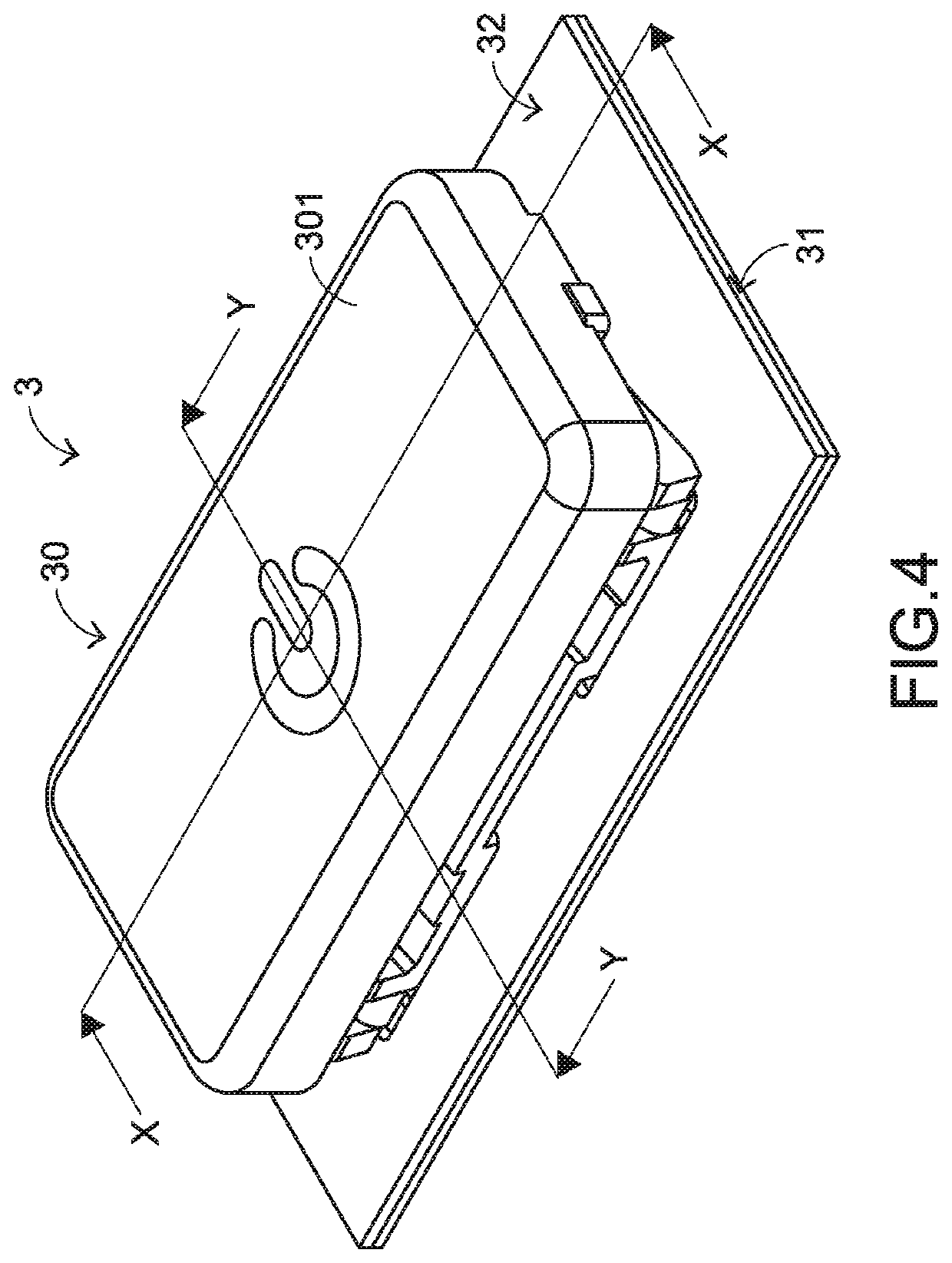
[0026]Please refer to FIGS. 4, 5, 6, 7 and 8. FIG. 4 is a schematic perspective view illustrating the appearance of a keyboard device according to a first embodiment of the present invention. FIG. 5 is a schematic exploded view illustrating a portion of the keyboard device as shown in FIG. 4 and taken along a first viewpoint. FIG. 6 is a schematic exploded view illustrating a portion of the keyboard device as shown in FIG. 4 and taken along a second viewpoint. FIG. 7 is a schematic cross-sectional view illustrating a portion of the keyboard device as shown in FIG. 4 and taken along the line XX. FIG. 8 is a schematic cross-sectional view illustrating a portion of the keyboard device as shown in FIG. 4 and taken along the line YY. For well understanding the present invention, the elements shown in the drawings are not in scale with the elements of the practical product and some components are not shown. For example, in FIGS. 5 and 6, the intermediate film layer and the lower film laye...


PUM


Abstract

A keyboard device includes a membrane circuit board, a base plate, a key structure and a light-emitting element. The key structure includes a keycap, a connecting element and an elastic element. The connecting element is arranged between the base plate and the keycap. The elastic element is arranged between the keycap and the membrane circuit board. The light-emitting element is electrically connected with the membrane circuit board and located under the elastic element. After the light beams from the light-emitting element are projected upwardly and transmitted through the elastic element, the light beams are uniformly projected to the keycap. Consequently, the keycap has the uniform illuminous efficacy.

Description

FIELD OF THE INVENTION[0001]The present invention relates to an input device and more particularly to a keyboard device.BACKGROUND OF THE INVENTION[0002]Generally, the widely-used peripheral input device of a computer system includes for example a mouse device, a keyboard device, a trackball device, or the like. Via the keyboard device, characters and symbols can be inputted into the computer system directly. As a consequence, most users and most manufacturers of input devices pay much attention to the development of keyboards.[0003]FIG. 1 is a schematic top view illustrating the outer appearance of a conventional keyboard device. As shown in FIG. 1, there are plural keys 10 on a surface of the conventional keyboard 1. These keys 10 are classified into several types, e.g. ordinary keys 101, numeric keys 102 and function keys 103. When one of these keys 10 is depressed by the user's finger, a corresponding signal is issued to the computer, and thus the computer executes a function co...

Claims


Application Information

Patent Timeline
Patent Type & Authority Applications(United States)
IPC IPC(8): H01H13/83G06F3/023H01H13/7065
CPCH01H13/83H01H13/7065G06F3/023G06F3/0202H01H3/125H01H2215/006H01H2219/014
Inventor LIN, YU-MING
Owner PRIMAX ELECTRONICS LTD
Why Eureka
Try Eureka