
Driving range based on past and future data

a technology of driving range and past and future data, applied in the direction of instruments, navigation instruments, computing models, etc., can solve the problems of reducing fuel economy, route may require more energy to traverse, inaccurate prediction of driving range, etc., and achieve the effect of outputing the future fuel economy of the vehicl

Active Publication Date: 2021-01-14
TOYOTA MOTOR NORTH AMERICA INC
View PDF0 Cites 9 Cited by
  • Summary
  • Abstract
  • Description
  • Claims
  • Application Information

AI Technical Summary

Benefits of technology

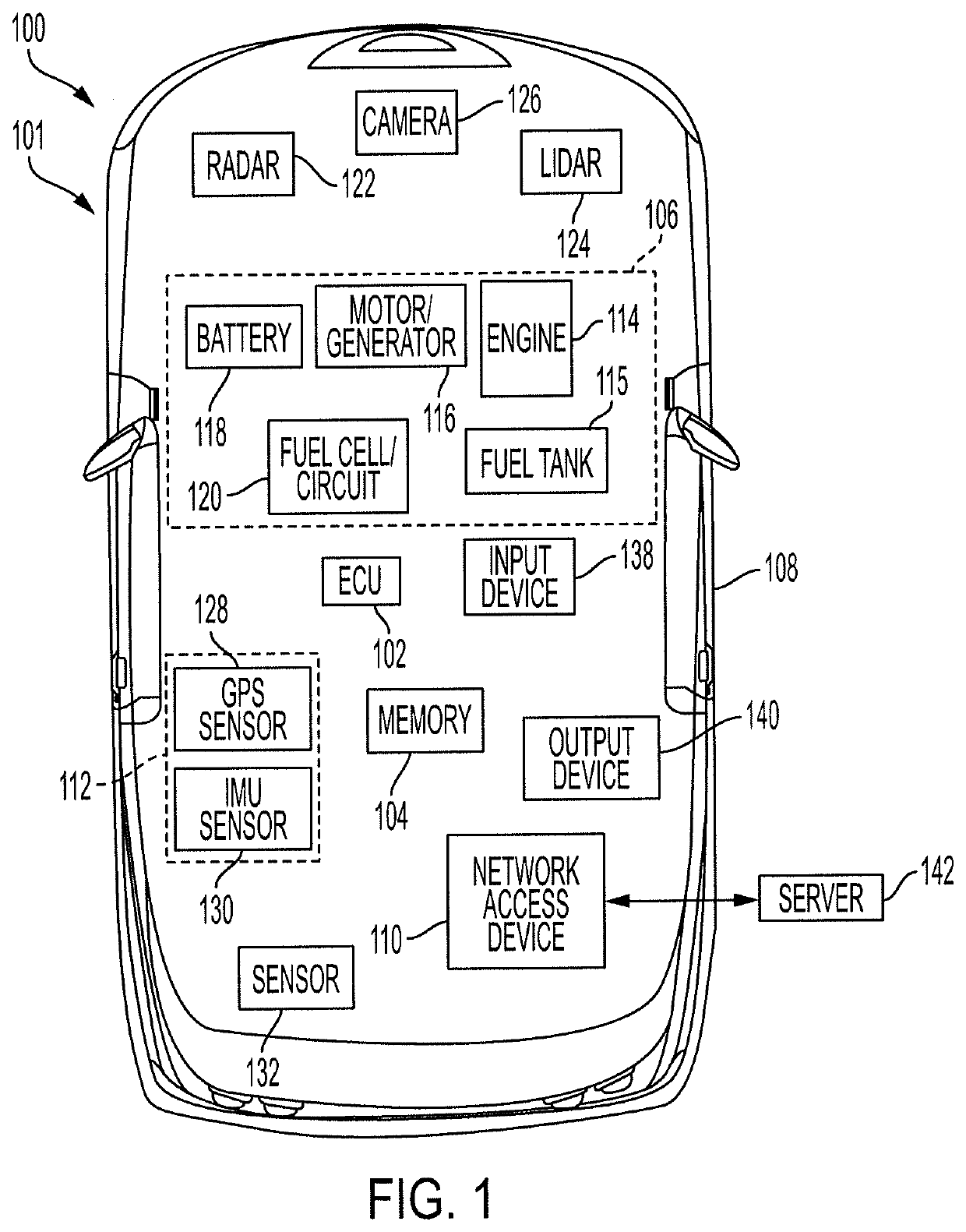
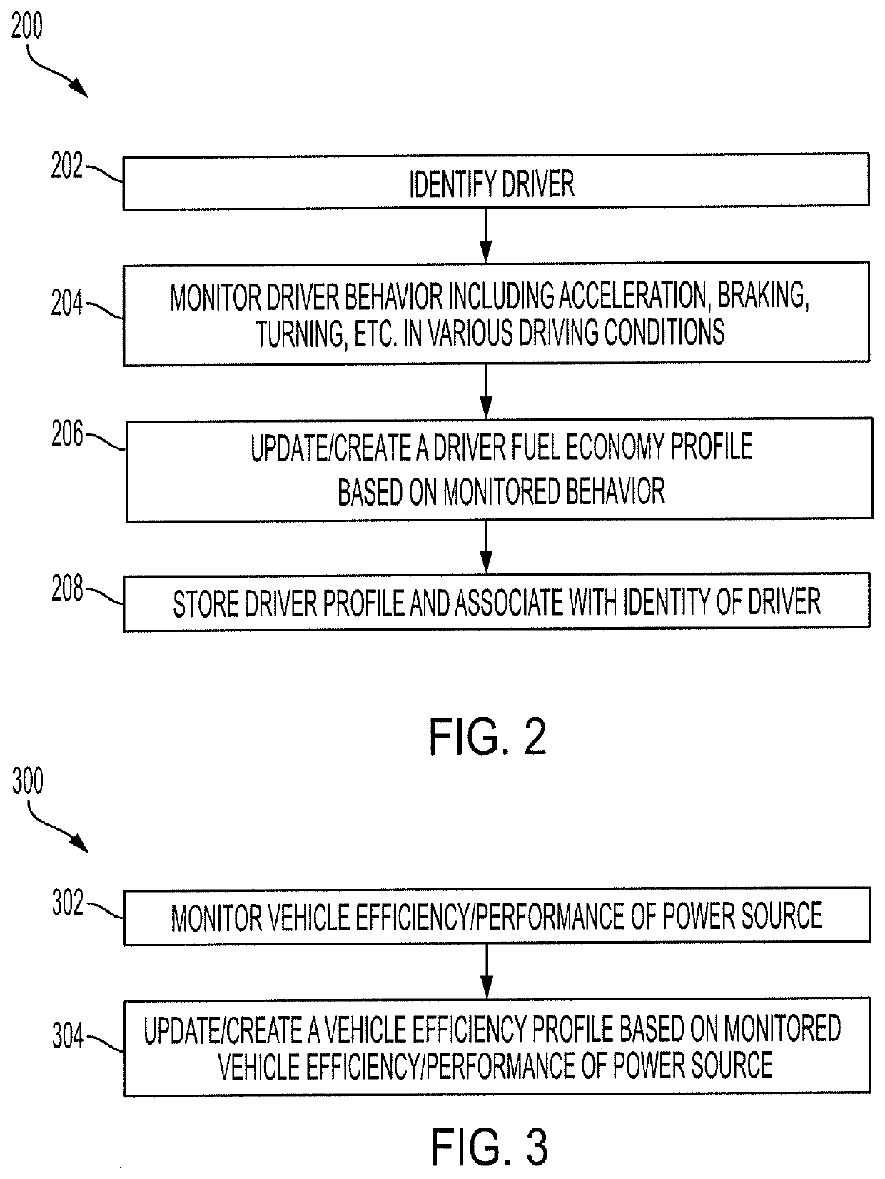
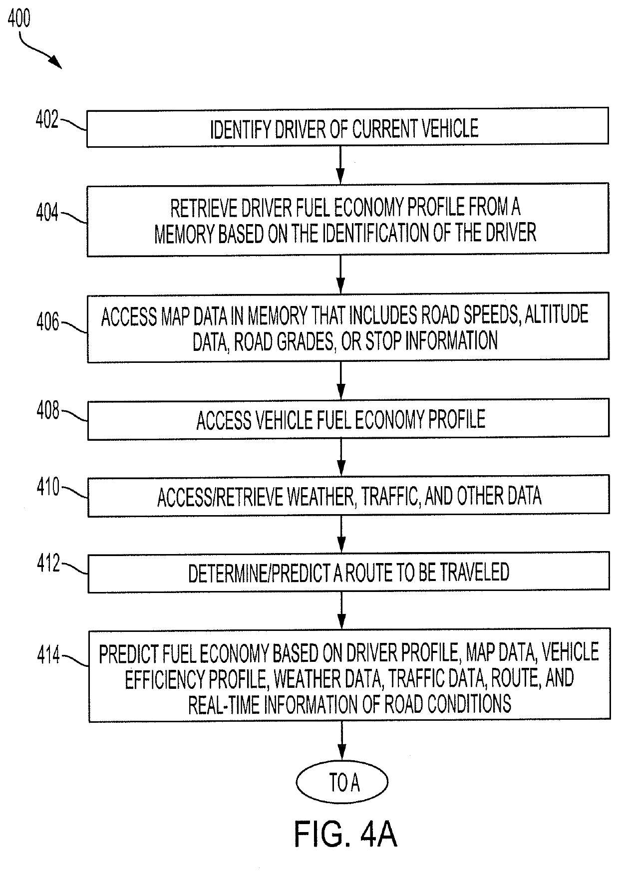
The patent describes a system and method for determining the range of a vehicle's driving range based on historical and forecasted data. The system includes an energy storage component for storing electrical or fuel, a power source for converting the stored energy or fuel into mechanical power, and a memory for storing map data and a driver profile based on the vehicle's driving behavior. The system also includes an electronic control unit for predicting the vehicle's future fuel economy based on the remaining energy level, the mapped data, and the driver profile. The driving range is then outputted through an output device. This technology allows for more accurate driving range information and improved fuel efficiency for vehicles.

Problems solved by technology

However, such predictions of driving range may be inaccurate for a variety of reasons.
Some drivers may drive in a fuel-efficient manner (e.g., slow accelerations, coasting), and other drivers may drive in a manner that reduces fuel economy.
In addition, some routes may require more energy to traverse than others.
In consequence, there is no upfront information about the expected fuel economy.
Also, some vehicles of the same make and model may experience different fuel efficiencies based on wear and tear of the engine or motor, state of tires, an amount of time elapsed since the vehicle has been serviced, or the like.

Method used


Image

  • Driving range based on past and future data
  • Driving range based on past and future data
  • Driving range based on past and future data

Examples


Embodiment Construction

[0012]The present disclosure describes systems and methods for providing accurate fuel economy and driving range data to a user. The systems provide advantages such as increased accuracy of fuel economy and driving range calculations, allowing a user to more comfortably predict when the vehicle will require recharging or refueling. The systems advantageously calculate the fuel economy and driving range based on specific driver profiles and specific vehicle profiles, thus allowing the increased accuracy to apply to a same driver in multiple vehicles. The systems provide additional benefits and advantages such as outputting a comparison of expected vehicle efficiency to actual vehicle efficiency, thus incentivizing a driver to drive in a more efficient manner. The systems also may provide tips to the driver that the driver may implement to increase efficiency, further advantageously incentivizing the driver to increase efficiency. This increased driver efficiency provides advantages s...


PUM


Abstract

A system for determining a driving range of a vehicle includes an energy storage component to store electrical energy or fuel. The system further includes a power source to convert the electrical energy or fuel into mechanical power to propel the vehicle. The system further includes a memory to store map data including road speeds, altitude data, road grades, or stop information corresponding to at least one of stop signs or stop lights, and a first driver profile corresponding to driving behavior of a first driver. The system further includes an electronic control unit (ECU) designed to predict the driving range of the vehicle based on an amount of the at least one of the electrical energy or fuel remaining in the energy storage component, the map data, and the first driver profile. The system further includes an output device designed to output the driving range of the vehicle.

Description

BACKGROUND1. Field[0001]The present disclosure relates to systems and methods for accurately predicting an efficiency and a driving range of a vehicle.2. Description of the Related Art[0002]Many vehicles now compute driving ranges as part of trip computer features. The paradigm that is used for computing this value focuses on assessing the fuel economy of the vehicle based on historical data and then estimating a driving range of the vehicle based on the available amount of fuel in a fuel tank. However, such predictions of driving range may be inaccurate for a variety of reasons. For example, different drivers drive vehicles in many different manners. Some drivers may drive in a fuel-efficient manner (e.g., slow accelerations, coasting), and other drivers may drive in a manner that reduces fuel economy. In addition, some routes may require more energy to traverse than others. For example, a route that includes a long uphill climb may require more energy than a route along flat terra...

Claims


Application Information

Patent Timeline
IPC IPC(8): G07C5/00B60W40/09G06N5/04
CPCG07C5/004G06N5/046B60W40/09G06N20/00G01C21/3469B60W50/14B60W2050/146B60W2556/50B60W2552/25B60W2552/15B60W2555/20B60W2555/60B60W2540/043B60W2540/30B60W50/0097B60W2510/244B60W2530/209B60W2556/10B60W2554/406B60W20/12G01C21/3484G01C21/3492B60K35/28B60K2360/169
Inventor SAAVEDRA ROMÁN, JOSÉ GUILLERMO
Owner TOYOTA MOTOR NORTH AMERICA INC
Learn More