Eureka AIR delivers breakthrough ideas for toughest innovation challenges, trusted by R&D personnel around the world.

Connection structure, forming method of connection structure and cable of connection structure

Active Publication Date: 2021-01-21
JAPAN AVIATION ELECTRONICS IND LTD
View PDF0 Cites 2 Cited by
  • Summary
  • Abstract
  • Description
  • Claims
  • Application Information

AI Technical Summary

Benefits of technology

The present invention provides a connection structure that allows for easy positioning of wires. The structure consists of two coverings that respectively enclose two wires and a hollow inside. When a part of the cable is pressed, the wires can be moved outward in the lateral direction, allowing them to be positioned easily. This setup makes it simple to connect wires in a cable.

Problems solved by technology

However, the positioning of the wires with the use of the existing locator is a cumbersome work.

Method used


Image

  • Connection structure, forming method of connection structure and cable of connection structure
  • Connection structure, forming method of connection structure and cable of connection structure
  • Connection structure, forming method of connection structure and cable of connection structure

Examples


Embodiment Construction

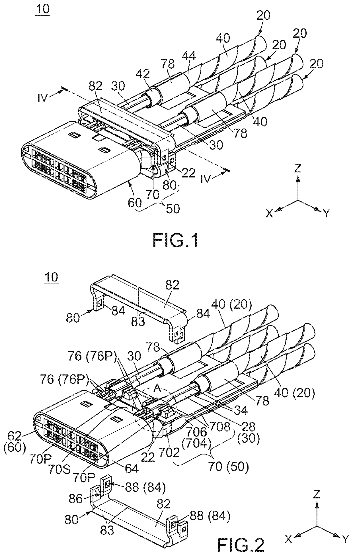
[0022]As shown in FIGS. 1 and 2, a connection structure 10 according to an embodiment of the present invention comprises four cables 20 and a connection object 50. The cables 20 have structures same as one another and are connected to the connection object 50 in the same way. However, the present invention is not limited thereto. For example, the cables 20 may have structures different from one another. Moreover, the number of the cables 20 of the connection structure 10 may be one or more.

[0023]Hereafter, explanation will be made about the structure of one of the cables 20. The following explanation is applicable to each of the cables 20 according to the present embodiment.

[0024]The cable 20 of the present embodiment includes an inner member 30 and an outer member 40. The inner member 30 is an inner structure of the cable 20 and extends along an extending direction of the cable 20. The outer member 40 covers the inner member 30 in a cable cross-section perpendicular to the extendin...


PUM


Abstract

A connection structure comprises a cable and a connection object. The cable includes two wires, two coverings and two coupling strips. The coverings cover the wires, respectively. Each of the coupling strips couples the two coverings to each other. The connection object comprises a base portion and a pressing member. The base portion has a catch portion and two side portions. The cable has a pressed section and a rear section located rearward of the pressing member in a front-rear direction (X-direction). The pressed section is sandwiched and pressed between the pressing member and the catch portion in an upper-lower direction (Z-direction) and is located between the two side portions in a lateral direction (Y-direction). In the lateral direction, a distance between the two wires of the pressed section is longer than another distance between the two wires of the rear section.

Description

CROSS REFERENCE TO RELATED APPLICATIONS[0001]This application is based on and claims priority under 35 U.S.C. § 119 to Japanese Patent Application No. JP2019-131181 filed Jul. 16, 2019, the content of which is incorporated herein in its entirety by reference.BACKGROUND OF THE INVENTION[0002]This invention relates to a connection structure comprising a cable and a connection object.[0003]For example, this type of connection structure is disclosed in JP2018-152244A (Patent Document 1), the content of which is incorporated herein by reference.[0004]Referring to FIG. 11, Patent Document 1 discloses a connection structure 90 comprising a cable 92 and a connector (connection object) 94. The cable 92 includes a plurality of wires 922. The connection object 94 comprises a board 96 and a locator 98. The board 96 is formed with a plurality of electrodes 962 which correspond to the wires 922, respectively. The electrodes 962 are arranged in a pitch direction. The locator 98 is formed with a pl...

Claims


Application Information

Patent Timeline
IPC IPC(8): H01R13/58H01R12/53H01R13/506
CPCH01R13/5812H01R13/506H01R12/53H01R13/502H01R13/56H01R43/0263H01R43/033H01B7/02H01R13/5808
Inventor TODA, KENTARO
Owner JAPAN AVIATION ELECTRONICS IND LTD
Why Eureka
Eureka Blog
Learn More