Indoor unit of an air conditioner

a technology of indoor unit and air conditioner, which is applied in the direction of space heating and ventilation, heating types, lighting and heating apparatus, etc., can solve the problems of not selectively conditioning the target area, the circulator cannot be used selectively, and the conditioned air cannot be remotely discharged, so as to reduce the flow loss of discharged air, prevent few formation, and reduce the effect of direct air flow discharg

Pending Publication Date: 2021-01-28
LG ELECTRONICS INC
View PDF4 Cites 3 Cited by
  • Summary
  • Abstract
  • Description
  • Claims
  • Application Information

AI Technical Summary

Benefits of technology

[0040]According to the present disclosure, an indoor unit of an air conditioner has one or more effects as follows.
[0041]First, for the air conditioner according to the present disclosure, there is an advantage in that a fan housing assembly is moved in a forward and rearward direction based on operation of an actuator, the fan housing assembly is moved through a front discharge outlet defined in a door assembly, the fan housing assembly provides a projection state in which a front end of the fan housing assembly protrudes further forward than a front surface of the door assembly, and the indoor unit of the air conditioner may provide conditioned air to a remote target area with direct air flow, in the projection state.
[0042]Second, according to the present disclosure, there is an advantage in that the indoor unit of the air conditioner may provide the conditioned air to the fan housing assembly moving forward or rearward in the cabinet assembly through an independent flow path.
[0043]Third, according to the present disclosure, there is an advantage in that, when the fan housing assembly is in the projection state, flow resistance between the direct air flow discharged by the steering grill and a cabinet assembly may be minimized
[0044]Fourth, according to the present disclosure, there is an advantage in that the steering grill protrudes out of the door assembly through a front discharge outlet to discharge the air to an indoor space, thereby minimizing flow loss of the discharged air.
[0045]Fifth, according to the present disclosure, there is an advantage in that the steering grill protrudes out of the door assembly through the front discharge outlet to discharge cooled air to the indoor space, thereby preventing few formation on a surface of the door assembly.

Problems solved by technology

There is a problem in that, as the indoor unit of the split-type air conditioner in related art includes an indoor fan disposed inside a cabinet, conditioned air may not be remotely discharged.
As the air circulator does not directly flow the conditioned air, there is a problem in that the air circulator may not supply the conditioned air to a target area in concentration and may not selectively condition the target area where temperature imbalance is generated.
For example, according to Korean Patent Publication No. 10-2017-0010293, the opening opened by the door unit is not suitable for remotely flowing the air.
In addition, according to Korean Patent Publication No. 10-2017-0010293, the door is moved forward to open the opening, and as a blowing fan is disposed inside an exterior panel, the air expelled by the blowing fan generates resistance to a structure inside the exterior panel, which causes a lot of flow loss to remotely flowing the air.

Method used


Image

  • Indoor unit of an air conditioner
  • Indoor unit of an air conditioner
  • Indoor unit of an air conditioner

Examples


second embodiment

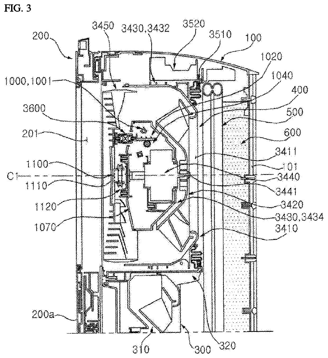
[0491]FIG. 27 is an exemplary cross-sectional view showing a steering grill moving forward according to the present disclosure.

[0492]According to the present disclosure, for a long-distance fan assembly, only a steering grill 13450 of a fan housing assembly is moved forward and the long-distance fan assembly includes an actuator 3471 to move the steering grill forward.

[0493]The actuator 3471 is disposed in a front fan housing 3430 and is disposed at a rear side of the steering base 1070. The actuator 3471 moves the steering base 1070 coupled to the steering grill 1070 in a forward and rearward direction.

[0494]A hydraulic cylinder is used as the actuator 3471.

[0495]The actuator 3471 is disposed in a space (S3) of the inner fan housing 3434. A rear end of the actuator 3471 is coupled to the motor mount 3442 and a front end thereof is coupled to the steering base 1070.

[0496]When the actuator 3471 is operated, the steering base 1070 and the steering grill 3450 are moved together forward...

first embodiment

[0499]In this embodiment, even when the steering grill 3450 is only moved forward, a steering assembly 1000 assembled to each of the steering grill 3450 and the steering base 1070 is moved together to implement steering of the steering grill 3450 described in the first embodiment in the same manner.

[0500]As the remaining configurations are the same as those in the first embodiment, details thereof are omitted below.


PUM


Abstract

An air conditioner may provide a a fan housing assembly that moves in the front-rear direction by the operation of an actuator, and the fan housing assembly moves so as to pass through a front outlet arranged on a door assembly to be in a projected state, and the front end of the fan housing assembly protrudes further to the front than the front surface of the door assembly; and through the projected state, may provide conditioned air by a direct air flow to a long-distance target region. The configuration may enable the minimization of interference between the discharged air and the door assembly, and the minimization of flow loss of the discharged air since, when the fan housing assembly is in the projected state, a steering grill is in a state of protruding to the outside of the door assembly by passing through the front outlet.

Description

TECHNICAL FIELD[0001]The present disclosure relates to an indoor unit of an air conditioner, and more particularly, to an indoor unit of an air conditioner including a long-distance fan assembly moving in a forward and rearward direction to be exposed to an outside of a cabinet assembly.BACKGROUND ART[0002]A split-type air conditioner may include an indoor unit disposed in an indoor space and an outdoor unit disposed in an outdoor space and may cool, heat, or dehumidify indoor air through refrigerants circulating between the indoor unit and the outdoor unit.[0003]Examples of indoor unit of the split-type air conditioner include a stand-type indoor unit vertically installed on the indoor floor, a wall-mounted indoor unit mounted on the indoor wall, and a ceiling-type indoor unit mounted on the indoor ceiling.[0004]There is a problem in that, as the indoor unit of the split-type air conditioner in related art includes an indoor fan disposed inside a cabinet, conditioned air may not be...

Claims


Application Information

Patent Timeline
Patent Type & Authority Applications(United States)
IPC IPC(8): F24F1/0018F24F1/0007F24F1/0011
CPCF24F1/0018F24F1/0011F24F1/0007F24F13/20F24F13/24F24F13/14F24F1/0029F24F1/005F24F11/79F24F2013/205F24F13/082F24F13/1426F24F2013/1446F24F2013/146
Inventor MUN, SEONGKUKBAE, JUNSEOKKIM, KANGYOUNGKIM, HAKIAELEE, EUNSUNLEE, TAEYUN
Owner LG ELECTRONICS INC
Why Eureka
Try Eureka