
Centrifugal compressor achieving high pressure ratio

a centrifugal compressor and high pressure technology, applied in the direction of machines/engines, supersonic fluid pumps, liquid fuel engines, etc., can solve the problem of limited pressure ratios within any given stag

Pending Publication Date: 2021-02-11
SIEMENS ENERGY INC
View PDF6 Cites 1 Cited by
  • Summary
  • Abstract
  • Description
  • Claims
  • Application Information

AI Technical Summary

Benefits of technology

The patent describes a compressor that can compress natural gas to high pressures with a high ratio of pressure to molecular weight. The compressor has a single-stage design with a centrifugal impeller and diffuser passage. The compressor can achieve high pressure ratios of at least 2.5:1 in a single-stage, and can be used in a multi-stage configuration. The compressor is modular in construction, with dimensions that can be adjusted to achieve different pressure ratios for different molecular weight process fluids. The technical effect of the invention is a compressor that can efficiently compress natural gas to high pressures with a high ratio of pressure to molecular weight.

Problems solved by technology

Achievable pressure ratios within any given stage are limited by ultimate mechanical stress limit of the impeller.

Method used


Image

  • Centrifugal compressor achieving high pressure ratio
  • Centrifugal compressor achieving high pressure ratio
  • Centrifugal compressor achieving high pressure ratio

Examples


Embodiment Construction

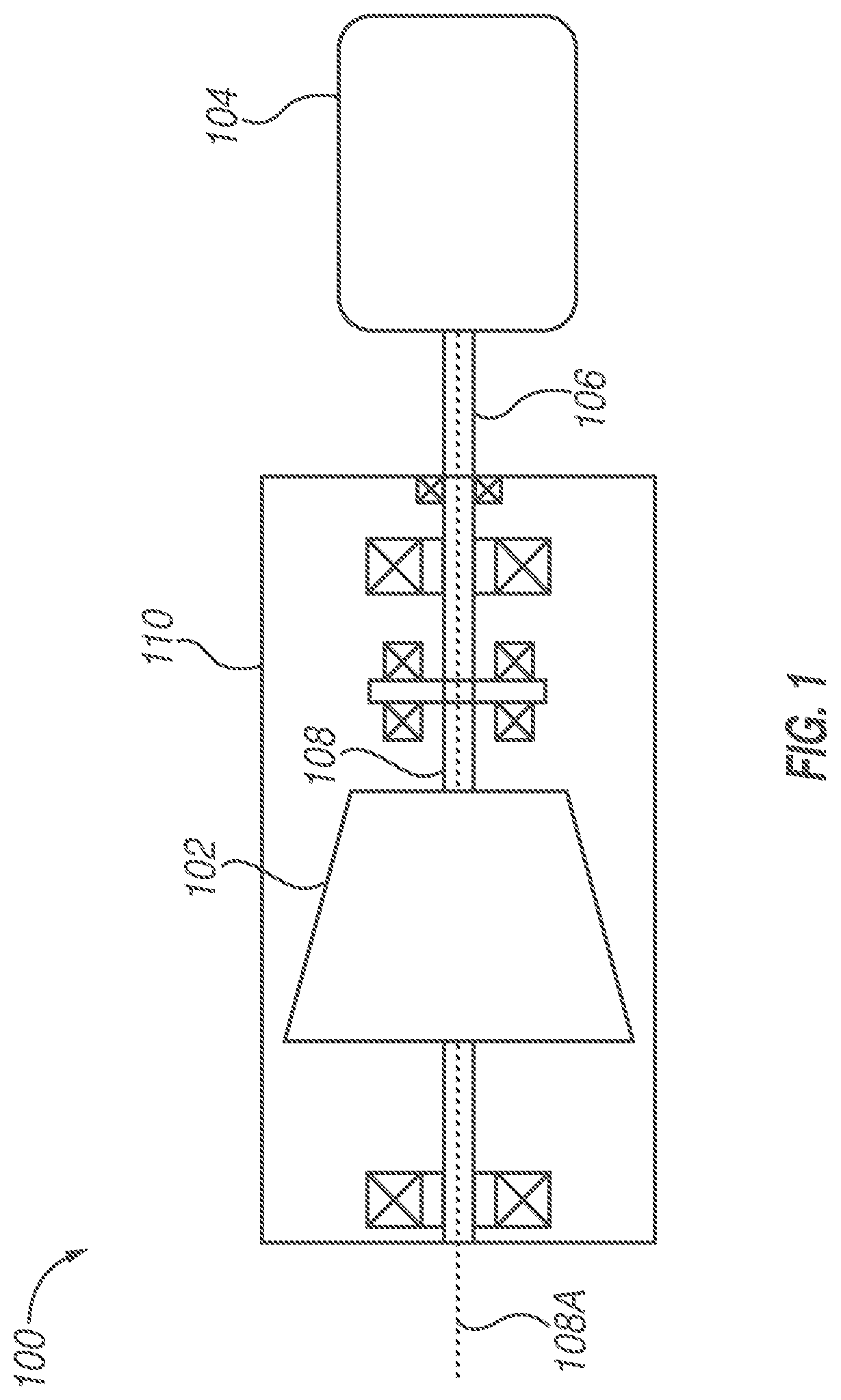
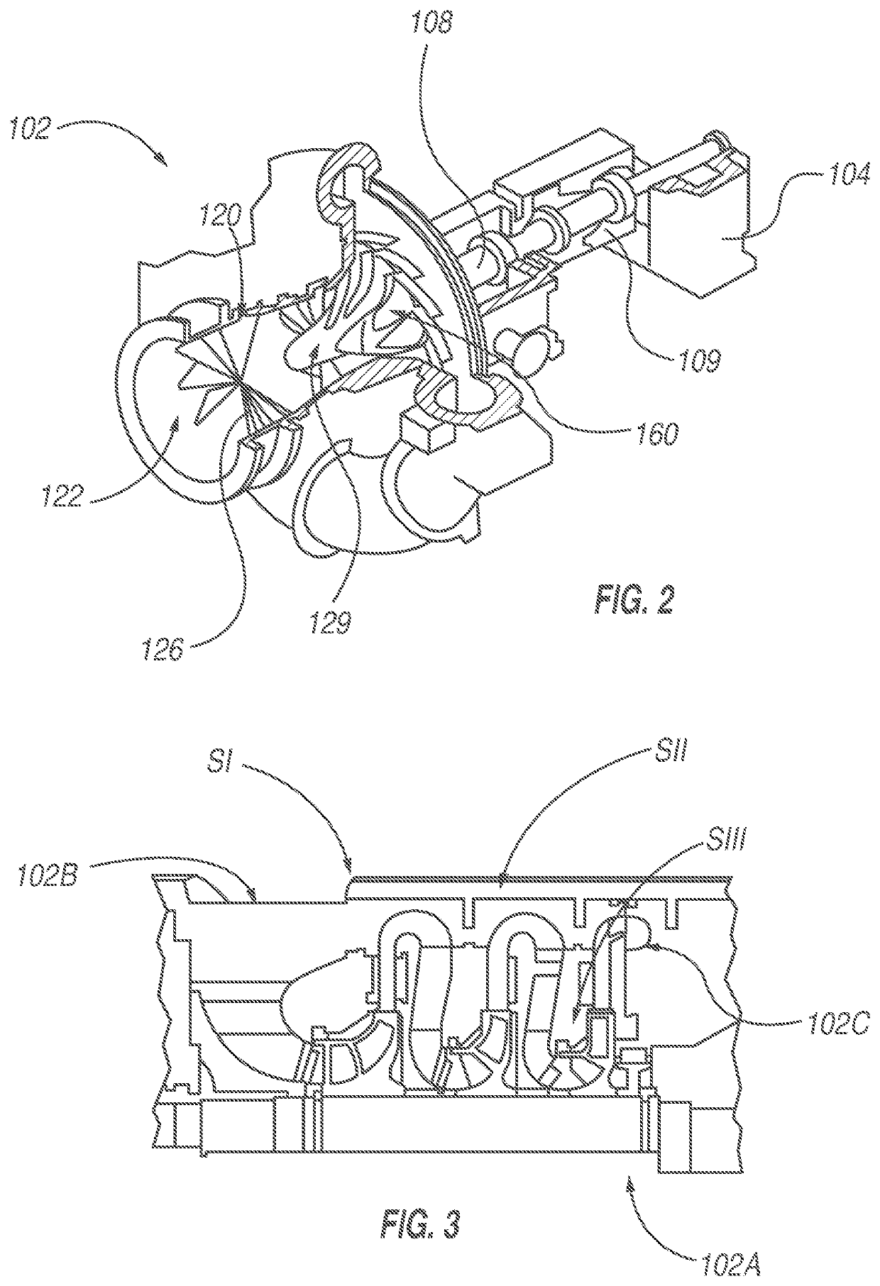
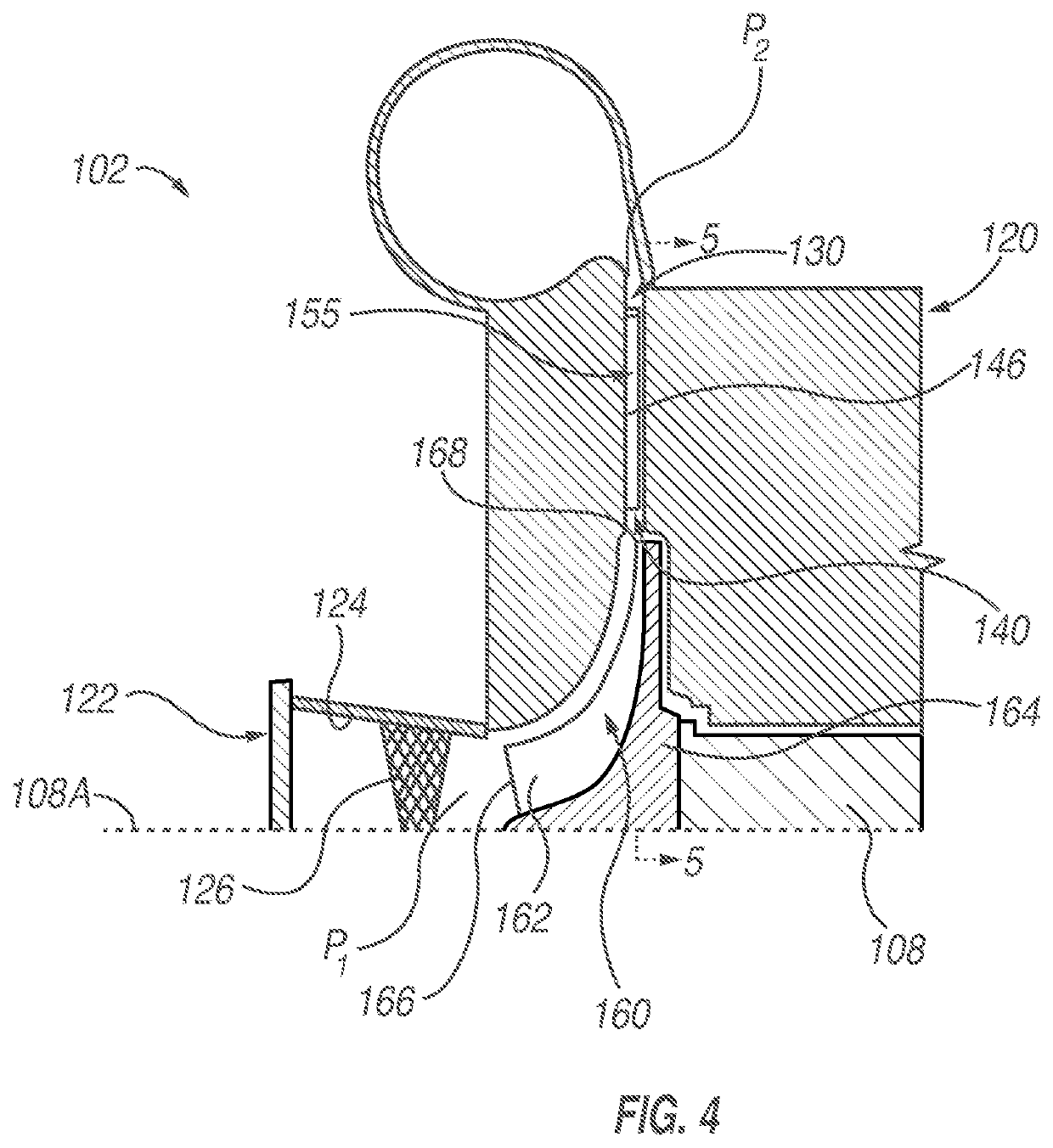
[0035]Exemplary embodiments of the invention are utilized in compressors, and methods of their operation. These exemplary embodiments achieve, in a single compressor stage, between the inlet and outlet of the stage, a high pressure ratio (r) of at least 5:1 on the process fluid having a molecular weight of 24-27.99; or at least 4:1 on a process fluid having a molecular weight of 20-24; or at least 3:1 on a process fluid having a molecular weight of 16-20 or at least 2.5:1 on a process fluid having a molecular weight of 10-16 or at least 2:1 on a process fluid having a molecular weight less than 10. By way of example, an exemplary embodiment achieves a pressure ratio (r) of greater than or equal to 2.5:1 on a process fluid having a molecular weight of 12-20, such as natural gas. Natural gas in that molecular weight range typically comprises methane, other hydrocarbons, and non-hydrocarbon constituents, such as water, and carbon dioxide. In at least one embodiment, the process fluids ...


PUM


Abstract

Compressors achieve in a single stage a high-pressure ratio (r) of greater than or equal to 2.5:1 on a process fluid having a molecular weight of 12-20, such as natural gas. Two or more of the compressor stages are combined serially to increase overall pressure ratio. Each single-stage includes respective inlet and outlet passages and an unshrouded, centrifugal impeller that includes a plurality of impeller blades. Process fluid is discharged from trailing edges of the impeller blades at a rotational velocity greater than or equal to 1400 feet / second into a diffuser passage of the outlet. Dimension ranges of the annular diffuser passage, the centrifugal impeller, and the diffuser vanes vary as a function of pressure ratio (r) and / or the flow coefficient (φ) of the process fluid flowing between the inlet and the outlet.

Description

PRIORITY CLAIM[0001]This application is a continuation-in-part of U.S. utility patent application Ser. No. 14 / 272,667, filed May 8, 2014, and entitled “Supersonic Compressor”, which claims the benefit of U.S. Provisional Application No. 61 / 823,237, filed May 14, 2013, and entitled “Supersonic Compressor”, both of which are incorporated by reference herein. Priority under the parent applications is claimed in all jurisdictions where it is permissible to do so.TECHNICAL FIELD[0002]The invention relates to centrifugal compressors. More particularly, in some embodiments, the invention relates to centrifugal compressors and methods of their operation, which in a single compressor stage, is capable of achieving high-pressure ratios of greater than, or equal to 2.5:1 on process fluids having a molecular weight range of 12-20, such as natural gas. In other embodiments, the invention relates to two-stage centrifugal compressors and methods of their operation, which are capable of achieving t...

Claims


Application Information

Patent Timeline
IPC IPC(8): F04D29/44F04D29/28F04D17/10F04D25/16F04D21/00
CPCF04D29/444F04D29/286F04D21/00F04D25/16F04D17/10F04D17/12F04D29/284
Inventor SOROKES, JAMES M.KUZDZAL, MARK J.EL GHAZZANI, EL MOSTAFALARDY, PASCAL
Owner SIEMENS ENERGY INC
Learn More