
Fuel cell unit

Active Publication Date: 2021-02-11
TOYOTA JIDOSHA KK
View PDF0 Cites 1 Cited by
  • Summary
  • Abstract
  • Description
  • Claims
  • Application Information

AI Technical Summary

Benefits of technology

The patent is about a fuel cell unit that has a case that is strong and sturdy enough to prevent damage to the fuel cell stack when it is impacted. This unit is designed to be compact and lightweight while still producing a significant amount of power. This solution is ideal for situations where a larger fuel cell stack is not necessary or desirable.

Problems solved by technology

When the case has reduced rigidity, a sufficient compressive load may not be applied to the stack.
However, when the case has reduced rigidity, a sufficient compressive load may not be applied to the stack as described above.

Method used


Image

  • Fuel cell unit
  • Fuel cell unit
  • Fuel cell unit

Examples


Embodiment Construction

General Configuration of Fuel Cell Unit 1

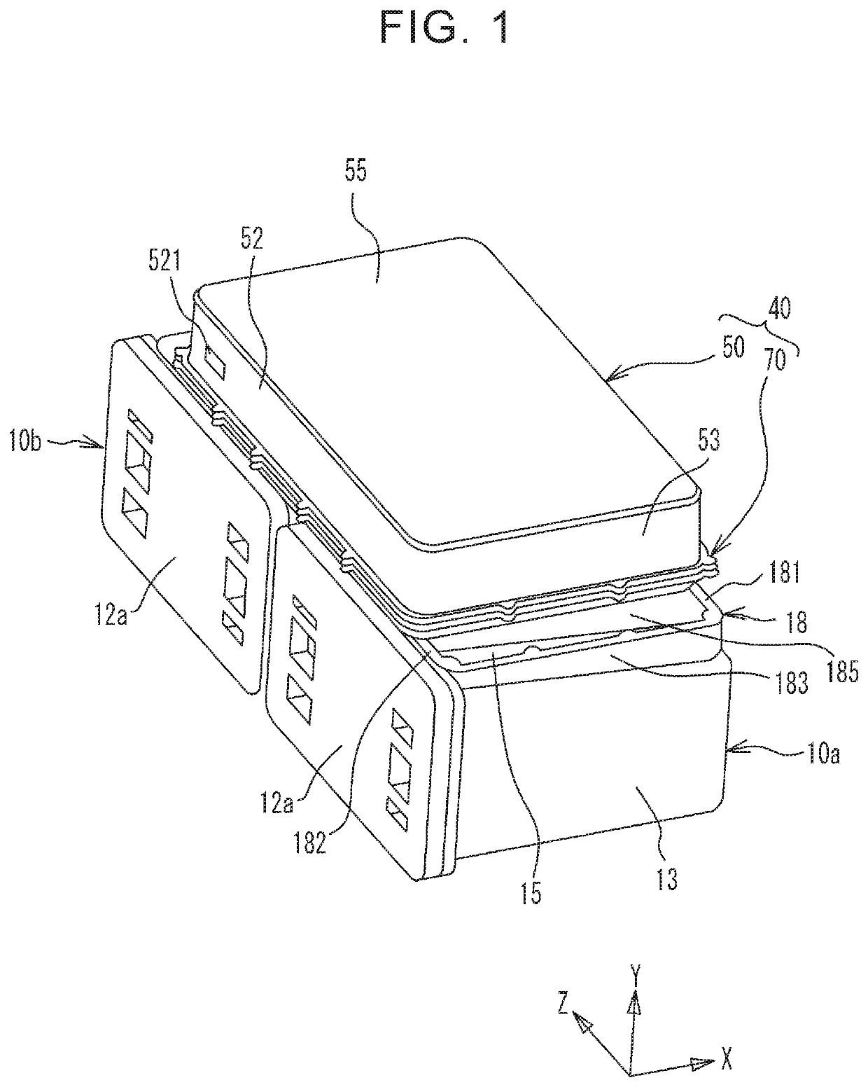
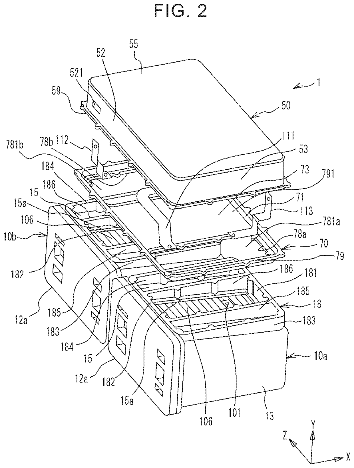
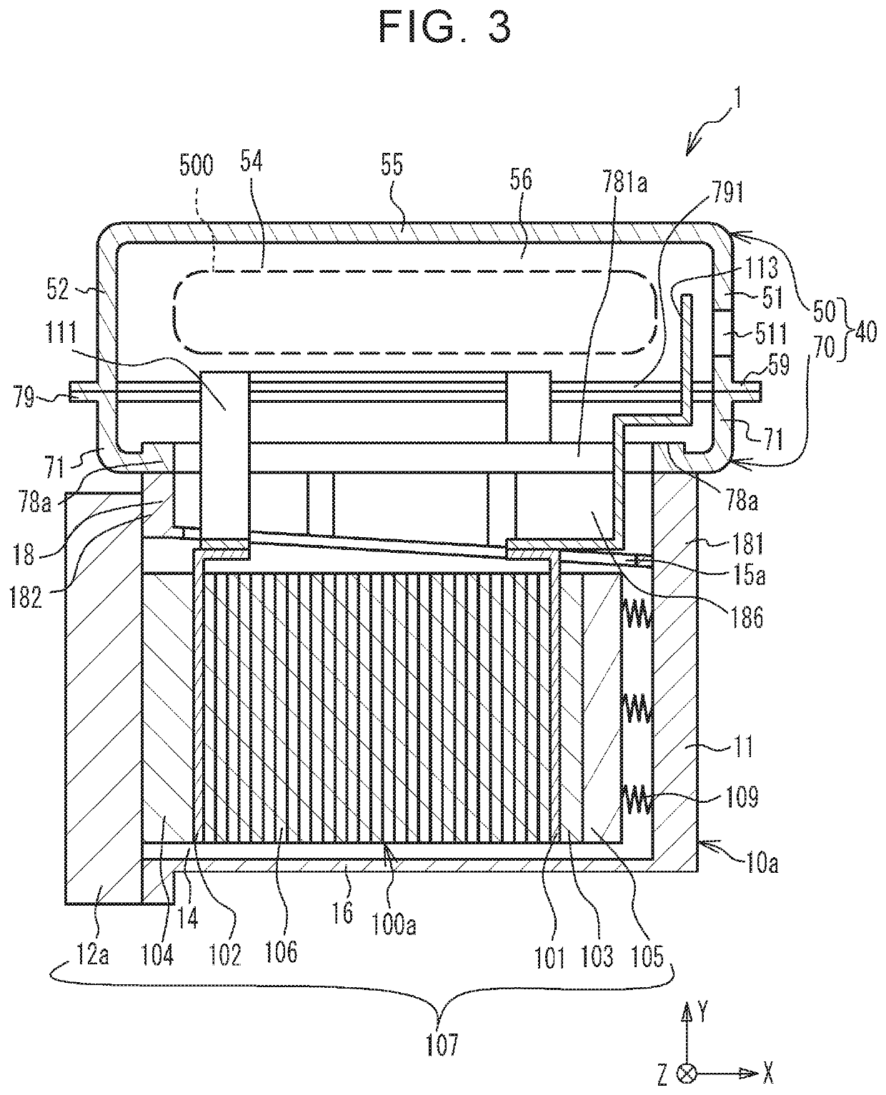
[0021]FIG. 1 is a perspective view of a fuel cell unit 1. FIG. 2 is an exploded perspective view of the fuel cell unit 1. FIGS. 3 and 4 are sectional views of the fuel cell unit 1. The fuel cell unit 1 includes two stack cases 10a, 10b, fuel cell stacks 100a, 100b, a boost converter 500, and a converter case 40. The fuel cell stacks 100a, 100b are accommodated in the stack cases 10a, 10b, respectively. The boost converter 500 is electrically connected to the fuel cell stacks 100a, 100b. The boost converter 500 is accommodated in the converter case 40. As described in detail later, the converter case 40 includes a body 50 and a lid 70. An X direction, a Y direction, and a Z direction that are orthogonal to each other are shown in the figures. The Z direction is an example of a direction in which the stack cases 10a, 10b are arranged next to each other. As described in detail later, the X direction is an example of a direction in which single c...


PUM


Abstract

A second flange is separated from at least one of ribs located at one end and the other end out of a plurality of ribs of a plurality of first cases which are located next to each other in a second direction, and is fixed to one of the ribs except for the at least one of the ribs.

Description

INCORPORATION BY REFERENCE[0001]The disclosure of Japanese Patent Application No. 2019-147424 filed on Aug. 9, 2019 including the specification, drawings and abstract is incorporated herein by reference in its entirety.BACKGROUND1. Technical Field[0002]The disclosure relates to fuel cell units.2. Description of Related Art[0003]There are cases where a fuel cell stack is integrated with a power converter for converting electric power of the fuel cell stack by fixing a case accommodating the power converter to a case accommodating the fuel cell stack with the fuel cell stack being electrically connected to the power converter (e.g., Japanese Patent Application Publication No. 2017-073199).SUMMARY[0004]The case accommodating the fuel cell stack has an opening so that a conductive member that electrically connects the fuel cell stack and the power converter can extend through the opening. The fuel cell stack has a stack in which a plurality of single cells are stacked. In order to obtai...

Claims


Application Information

Patent Timeline
IPC IPC(8): H01M8/2475H01M8/249H01M8/04828
CPCH01M8/2475H01M2250/20H01M8/0494H01M8/249Y02E60/50Y02T90/40
Inventor ITOU, MASAYUKI
Owner TOYOTA JIDOSHA KK
Learn More