Pipe structure, truss structure, and artificial satellite using the same
- Summary
- Abstract
- Description
- Claims
- Application Information
AI Technical Summary
Benefits of technology
Problems solved by technology
Method used
Image

Examples
embodiment 1
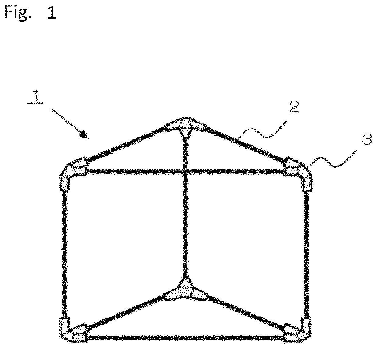
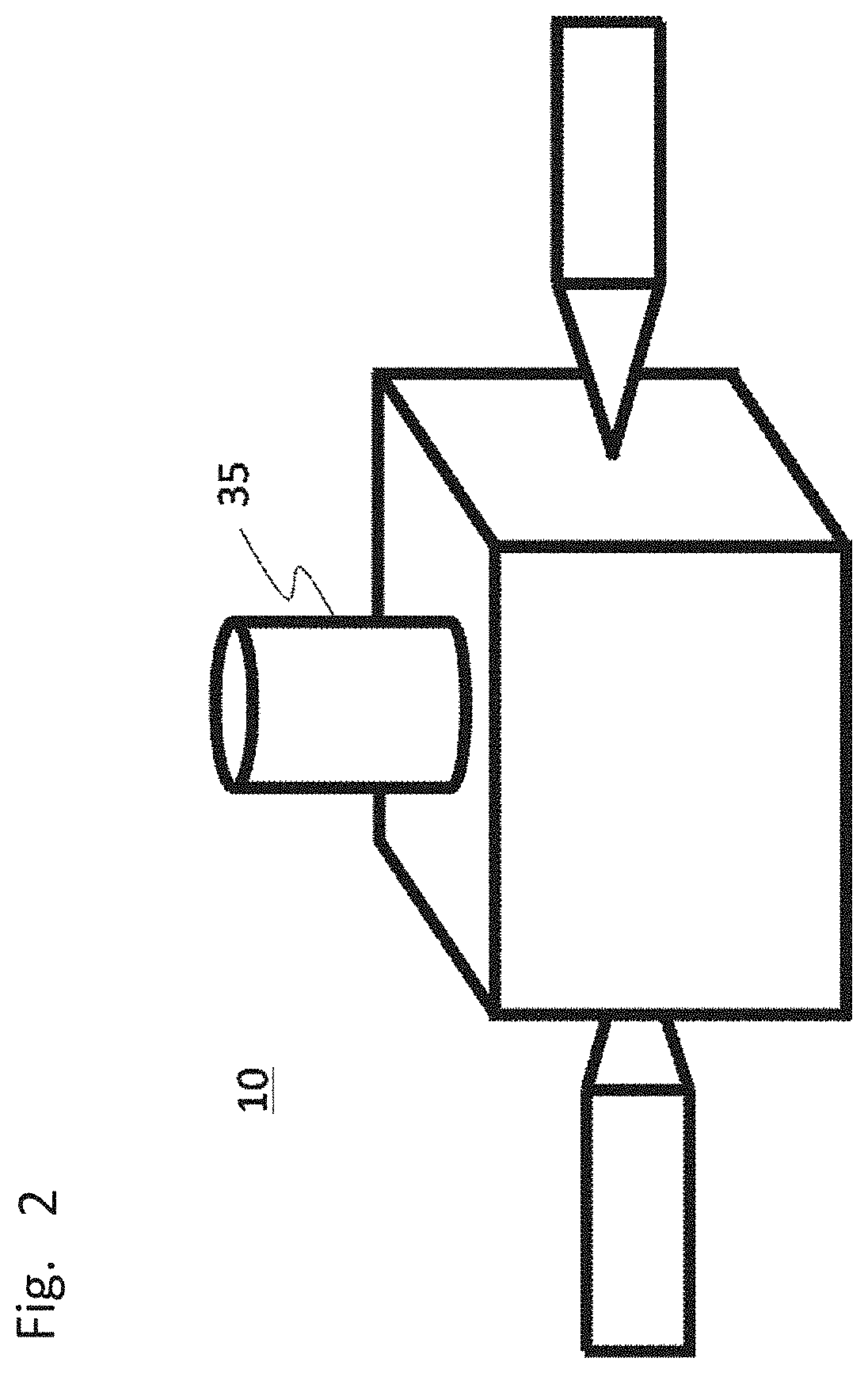
[0025]FIG. 1 is a schematic view of a truss structure of Embodiment 1 for carrying out the present disclosure. As shown in FIG. 1, a truss structure 1 of the present embodiment is composed of pipe structures 2 and joints 3. FIG. 2 is a schematic view of an artificial satellite 10 using the truss structure 1 of the present embodiment. As shown in FIG. 2, the truss structure 1 of the present embodiment is a support structure which is three-dimensionally structured to support a reflector 35 and the like mounted on an artificial satellite.
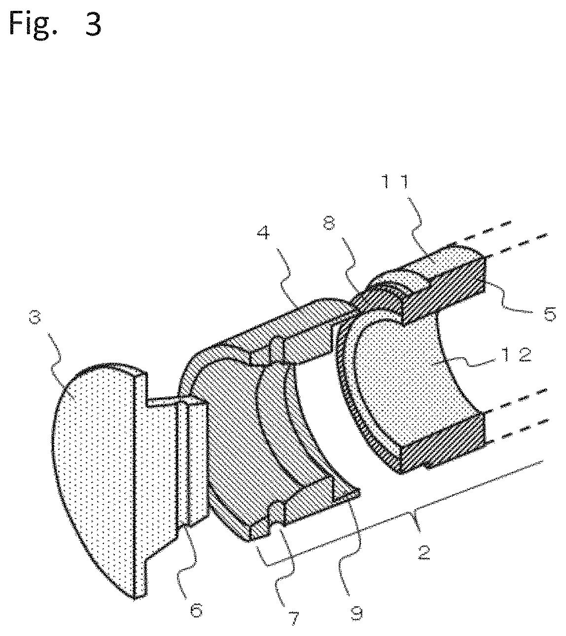
[0026]FIG. 3 is a perspective view of the cross-section of the joint portion between the pipe structure 2 and the joint 3 of the present embodiment. In FIG. 3, each of its parts is shown disassembled for easy understanding, but in reality, all parts are fastened together.
[0027]As shown in FIG. 3, the pipe structure 2 includes an intermediate part 4 for being fastened to the joint 3, the pipe 5, and moisture-proof foils 11 and 12. The intermediate parts...
embodiment 2
[0057]The pipe structure of Embodiment 1 has one protrusion at each end of the pipe; in Embodiment 2, a pipe structure provided with two or more protrusions will be described.
[0058]FIGS. 9 are illustrative views showing a manufacturing process of a pipe structure 2 in the present embodiment. FIG. 9(e) is a schematic view of the pipe structure 2 when a laminating process is completed. As shown in this figure, a plurality of split intermediate parts 4a to 4d is prepared as the intermediate part 4. Each of the split intermediate parts 4a to 4d has a recessed portion corresponding to each of the protrusions of the pipe. The pipe is formed of a prepreg laminate 22 that is made by layering a plurality of prepregs 22a.
[0059]First, as shown in FIG. 9(a), a moisture-proof foil 12 being the foil of the inner circumferential side is placed on the mandrel 21; and then, a plurality of prepregs 22a is stacked on top of it. At this moment, the lengths of the prepregs 22a in the axial direction ar...
embodiment 3
[0069]In the pipe structures described in Embodiment 1 and Embodiment 2, it is important that the end portions of the moisture-proof foils are tightly sandwiched between the pipe and the intermediate parts. In Embodiment 3, another configuration will be described in which the end portions of the moisture-proof foils are tightly sandwiched between the pipe and the intermediate parts.
[0070]FIG. 10 is a cross-sectional schematic view of a pipe structure 2 of the present embodiment. The pipe structure of the present embodiment is a pipe structure which includes the plurality of protrusions described in Embodiment 2, and FIG. 10 shows the protrusion located at the radially outermost circumference. As shown in FIG. 10, the protrusion 8 located at the outermost circumference of the pipe 5 of the present embodiment is composed of four layered prepregs 22a.
[0071]Among the four layered prepregs 22a, the two radially inner prepregs 22a are set so as to have their carbon fiber orientations par...
PUM
| Property | Measurement | Unit |
|---|---|---|
| Dimensional stability | aaaaa | aaaaa |
| Coefficient of linear thermal expansion | aaaaa | aaaaa |
Abstract
Description
Claims
Application Information
 - R&D Engineer
- R&D Manager
- IP Professional
- Industry Leading Data Capabilities
- Powerful AI technology
- Patent DNA Extraction
Browse by: Latest US Patents, China's latest patents, Technical Efficacy Thesaurus, Application Domain, Technology Topic.
© 2024 PatSnap. All rights reserved.Legal|Privacy policy|Modern Slavery Act Transparency Statement|Sitemap