Sliding component

a technology of sliding components and components, applied in the direction of bearing components, shafts and bearings, bearing seals, etc., can solve problems such as the development of technology beyond the limits of the conventional arts

Active Publication Date: 2021-02-25
EAGLE INDS
View PDF0 Cites 3 Cited by
  • Summary
  • Abstract
  • Description
  • Claims
  • Application Information

AI Technical Summary

Benefits of technology

[0023]The present invention achieves the following outstanding effects:

Problems solved by technology

However, due to growing awareness of environmental problems in recent years, further improvements in the performance of mechanical seals have been required, and technical development beyond the limits of the conventional arts has been necessary.

Method used


Image

  • Sliding component
  • Sliding component
  • Sliding component

Examples


first embodiment

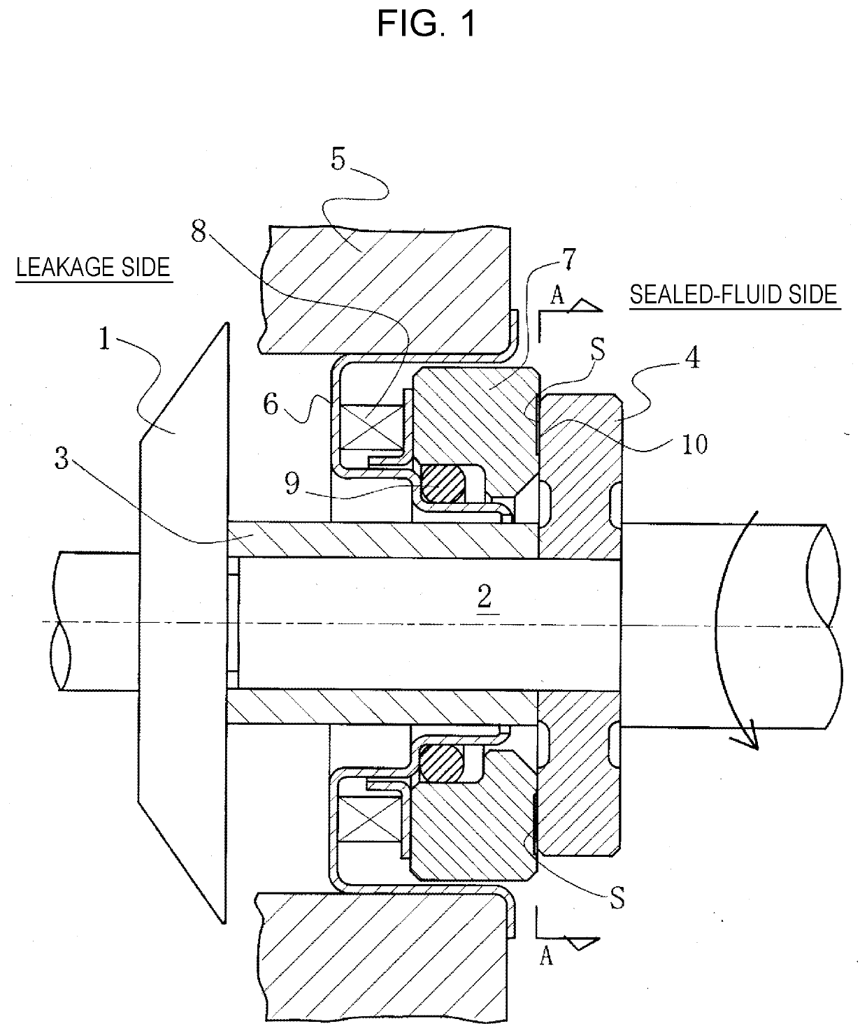
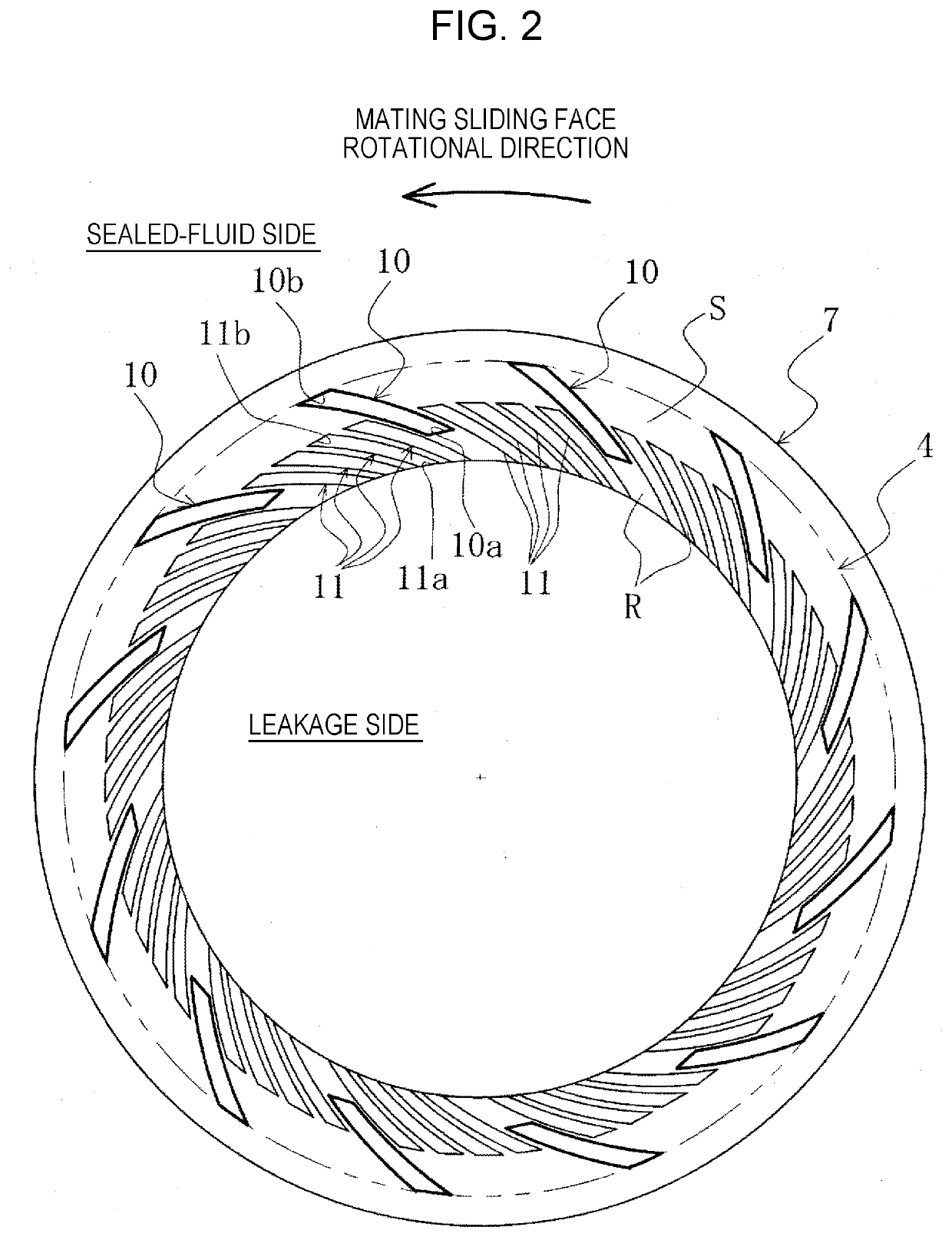
[0029]With reference to FIGS. 1 and 2, a sliding component according to a first embodiment of the present invention will be described.

[0030]Note that the embodiments below describe a mechanical seal, which is an example of a sliding component, as an example. The outer peripheral side of sliding parts constituting the mechanical seal is described as the sealed-fluid side (liquid side or misty-fluid side), and the inner peripheral side as the leakage side (gas side). However, the present invention is not limited to this, and is applicable to a case where the outer peripheral side is the leakage side (gas side), and the inner peripheral side is the sealed-fluid side (liquid side or misty-fluid side). As for the relationship in the magnitude of pressure between the sealed-fluid side (liquid side or misty-fluid side) and the leakage side (gas side), for example, the sealed-fluid side (liquid side or misty-fluid side) may be at high pressure, and the leakage side (gas side) at low pressur...

second embodiment

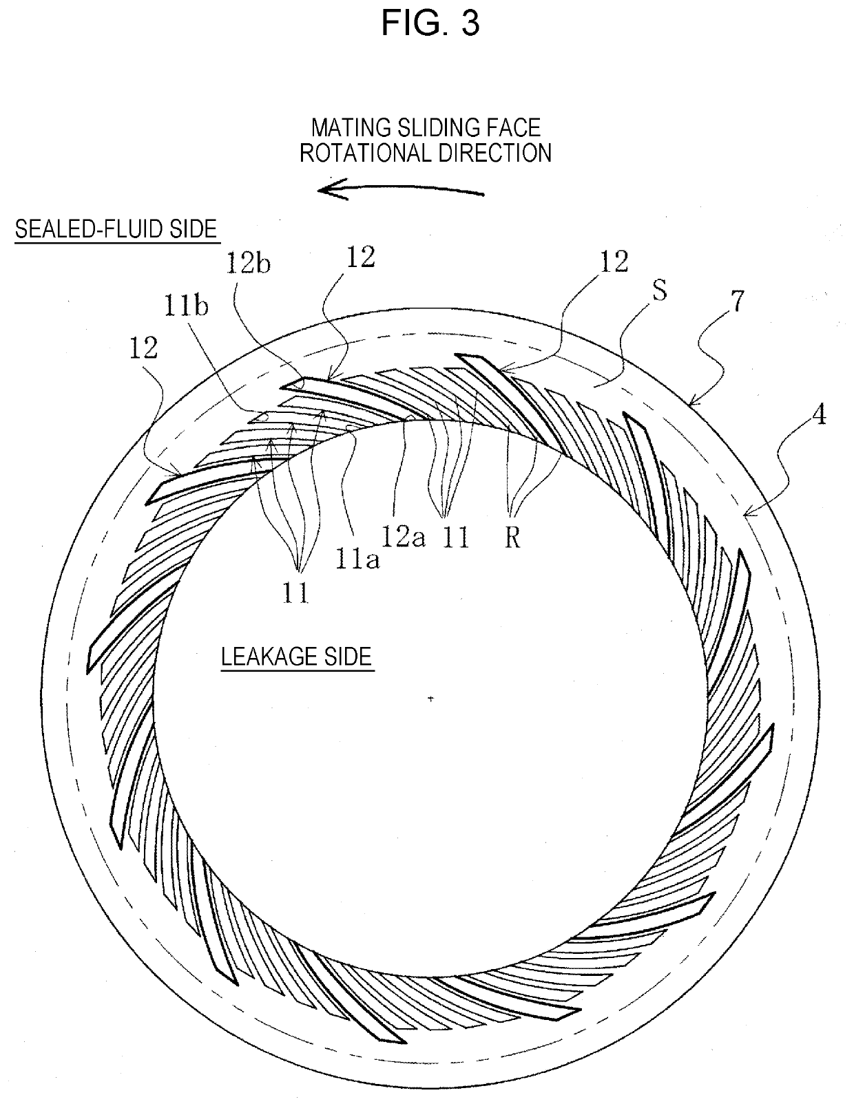
[0057]With reference to FIG. 3, a sliding part according to a second embodiment of the present invention will be described.

[0058]The sliding part according to the second embodiment is different from the sliding part of the first embodiment in that discharge grooves are inner peripheral discharge grooves. The other basic configuration thereof is identical to that of the first embodiment, and the same reference numeral is assigned to the same member as that in the first embodiment without duplicated explanation.

[0059]In FIG. 3, the sliding face S is provided with discharge grooves 12 disposed at an angle such that their upstream ends 12a are located on the leakage side and their downstream ends 12b are located on the sealed-fluid side.

[0060]The discharge grooves 12 extend radially with a constant width, are provided at an angle to facilitate the flow of fluid from the upstream ends 12a to the downstream ends 12b by relative sliding, and are of a spiral shape or a rectangular shape, fo...

third embodiment

[0067]With reference to FIG. 4, a sliding part according to a third embodiment of the present invention will be described.

[0068]The sliding part according to the third embodiment is different from the sliding part of the first embodiment in that it includes as discharge grooves both those of the outer peripheral discharge groove type and those of the inner peripheral discharge groove type. The other basic configuration thereof is identical to that of the first embodiment, and the same reference numeral is assigned to the same member as that in the first embodiment without duplicated explanation.

[0069]In FIG. 4, the sliding face S is provided with both discharge grooves 10 of the outer peripheral discharge groove type and discharge grooves 12 of the inner peripheral discharge groove type.

[0070]In the case of FIG. 4, the discharge grooves 10 of the outer peripheral discharge groove type and the discharge grooves 12 of the inner peripheral discharge groove type, the numbers of which ar...


PUM


Abstract

In an exemplary embodiment, a sliding component includes a pair of sliding parts sliding relatively to each other. One sliding part is a stationary-side seal ring 7, and the other sliding part is a rotating-side seal ring 4, wherein the seal rings have sliding faces S formed radially for sealing a liquid or a misty fluid as a sealed fluid against leakage. At least one of the sliding faces S is provided with: spiral grooves 11 which have upstream ends 11a connected to a leakage side, and downstream ends 11b not connected to a circumferential edge on a sealed-fluid side, and are disposed at an angle from upstream to downstream; and discharge grooves 10 disposed at an angle such that their upstream ends 10a are located on the leakage side and their downstream ends 10b are located on the sealed-fluid side.

Description

TECHNICAL FIELD[0001]The present invention relates to sliding components suitable, for example, for mechanical seals, bearings, and other sliding units. In particular, the present invention relates to sliding components such as seal rings that require reduction of friction by intervention of fluid between their sliding faces as well as prevention of leakage of fluid from the sliding faces, for example, oil seals used in gearboxes for turbochargers or for aircraft engines, or bearings.BACKGROUND ART[0002]Mechanical seals, which are an example of sliding components, are evaluated for their performance, based on their leakage rate, wear rate, and torque. Conventional arts have optimized the sliding materials and the sliding face roughness of mechanical seals, thereby enhancing performance and achieving low leakage, long life, and low torque. However, due to growing awareness of environmental problems in recent years, further improvements in the performance of mechanical seals have been...

Claims


Application Information

Patent Timeline
Patent Type & Authority Applications(United States)
IPC IPC(8): F16J15/34F16C33/10
CPCF16J15/3412F16C33/74F16C33/107F16C33/1065F16C2360/24F16C2360/23F16C33/106F16J15/3416
Inventor KIMURA, WATARUTOKUNAGA, YUICHIRONEGISHI, YUTAHOSOE, TAKESHIINOUE, HIDEYUKIIGUCHI, TETSUYA
Owner EAGLE INDS
Why Eureka
Try Eureka