Traction control rollback mitigation on split mu grades

a technology of traction control and split mu, which is applied in the direction of brake systems, vehicle components, propulsion unit safety devices, etc., can solve the problems of disconcerting vehicle rollback, tire failure to contribute significantly to uphill climb, and vehicle rollback, so as to reduce vehicle rollback, minimize vehicle rollback, and reduce vehicle rollback

Pending Publication Date: 2021-03-04
ZF ACTIVE SAFETY US INC
View PDF3 Cites 1 Cited by
  • Summary
  • Abstract
  • Description
  • Claims
  • Application Information

AI Technical Summary

Benefits of technology

[0005]An advantage of the invention is a detection of a vehicle wheel slip condition immediately following a Hill start assist operation. The system monitors both wheel slip and backward movement of the vehicle after de-actuation of the vehicle brakes immediately following the Hill start assist operation. Upon detection of rollback, an undriven (including a non-dominant or less dominantly driven wheel) wheel having the highest mu, traction or grip relative to the road surface is identified and the vehicle brake of that respective undriven wheel is re-actuated to reduce rollback of the vehicle. The braking force applied to the undriven wheel is proportional to the wheel speed of the wheel (or other estimation of vehicle speed), such that the all the brake pressure returns to zero when the vehicle is ending the rollback and preparing to move forward.
[0006]An embodiment contemplates a stability control system of a vehicle utilizing an electronic control unit that minimizes rollback of a vehicle as a result of wheel slip immediately following a hill start assist operation. A plurality of wheel speed sensors measure each of the vehicle wheel speeds. A slope of a road surface is determined. An electronic control unit includes an electronic braking control module. The electronic braking control module controls actuation and de-actuation of vehicle brakes on an inclined surface. Immediately following a hill start assist operation on the inclined surface after each wheel brake is de-actuated for allowing movement of the vehicle up the hill, a split-mu road surface condition is detected in response to sensing wheel slip for each of the wheels. The electronic control unit determines a respective undriven wheel having the highest coefficient of friction at a tire / road surface interface among the undriven wheels as determined by the wheel speeds. The electronic braking control module actuates the vehicle brake of the undriven wheel having the highest coefficient of friction at the tire / road surface interface for reducing rollback of the vehicle. The braking of the undriven, or non-dominant driven, wheel is in addition to any standard stability control braking that may already be occurring.
[0007]A method of minimizing rollback of a vehicle as a result of wheel slip immediately following a hill start assist operation. Wheel speeds are sensed for each of the plurality of wheels of the vehicle. Sensing that the vehicle is on an inclined surface. Each vehicle brake actuator is de-actuated upon completion of a hill start assist operation. A rollback condition of the vehicle is determined after release of the each of the vehicle brakes. A wheel slip condition is detected for each undriven, or non-dominant driven, wheel. A split-mu road surface is determined to be between the undriven wheels of the vehicle. A determination is made of which respective undriven wheel has the highest coefficient of friction at the tire / road surface interface. An electronic braking control module actuates the vehicle brake of the undriven wheel having the highest coefficient of friction at the tire / road surface interface for reducing the movement of the vehicle rearward down the hill. The braking of the undriven, or non-dominant driven, wheel is in addition to any standard stability control braking that may already be occurring.

Problems solved by technology

During the time a driver removes its foot from the brake pedal and applies the acceleration pedal where a presumed to be sufficient amount of propulsive torque is generated to propel the vehicle in an ascending direction, rollback of the vehicle may occur where there is insufficient propulsive torque to propel the vehicle up the hill.
Typically, brake pressure to hold the vehicle at rest on the hill is released before any wheel slip occurs to indicate that some of the tires will not be able to contribute significantly to the uphill climb.
The result is a disconcerting vehicle rollback when the driver's intention is to climb the hill.
In addition, vehicle loading such as towing, passenger weight distribution, and hill grades that approach traction and engine power limits of a given vehicle factor into this issue.
While traction control does its best to quickly find the optimal propulsive torque and cross-differential braking, there can still be significant rollback during the initial phase of the hill start launch attempt if wheel slip occurs on at least one of the driven wheels.

Method used


Image

  • Traction control rollback mitigation on split mu grades
  • Traction control rollback mitigation on split mu grades
  • Traction control rollback mitigation on split mu grades

Examples


Embodiment Construction

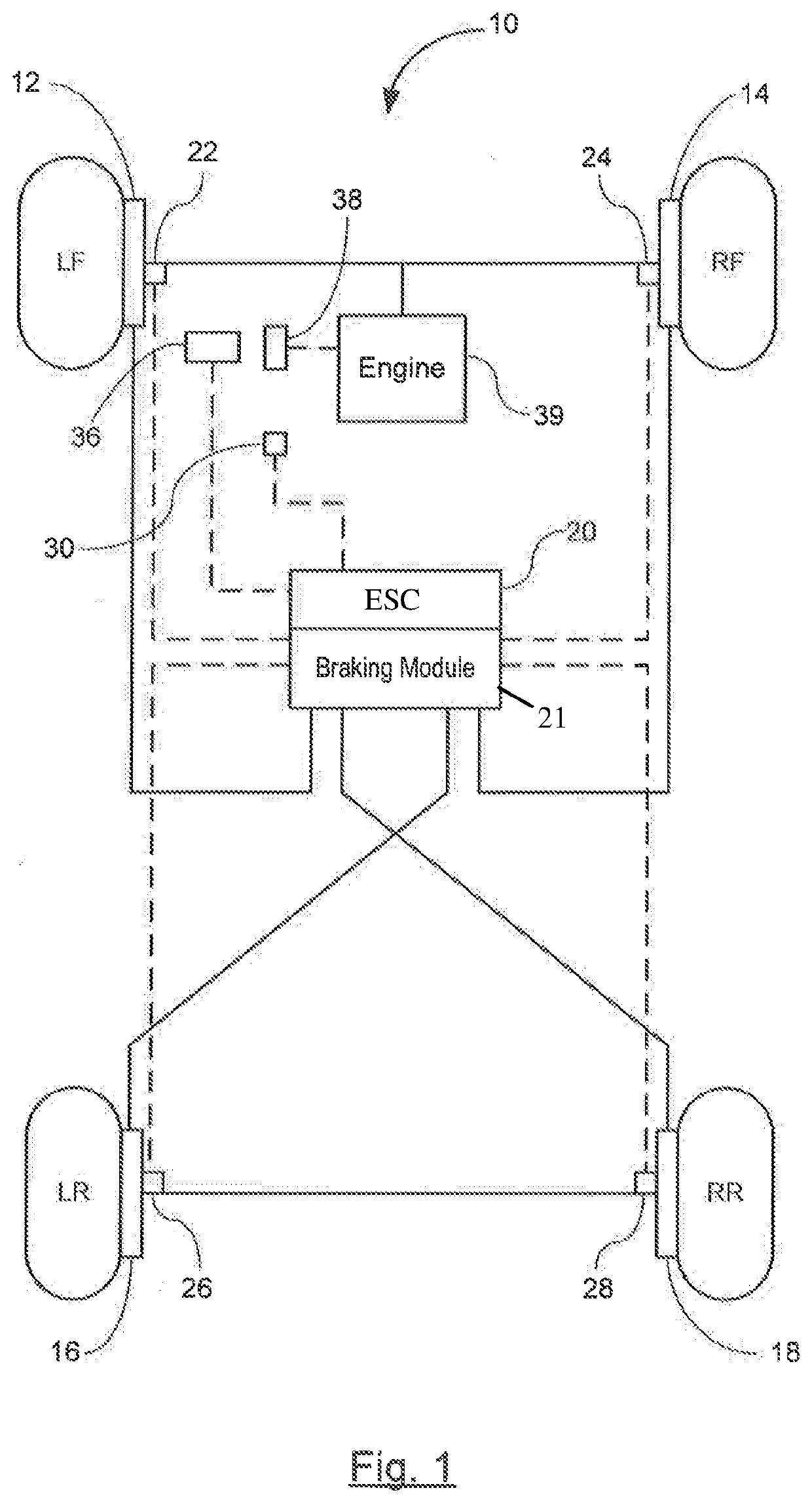
[0013]Referring now to the drawings, there is shown in FIG. 1 a vehicle 10 having a stability control system in accordance with the invention for stability controls. The stability control system may suitably be used on a ground vehicle such as an automotive vehicle having four wheels and a brake for each wheel.

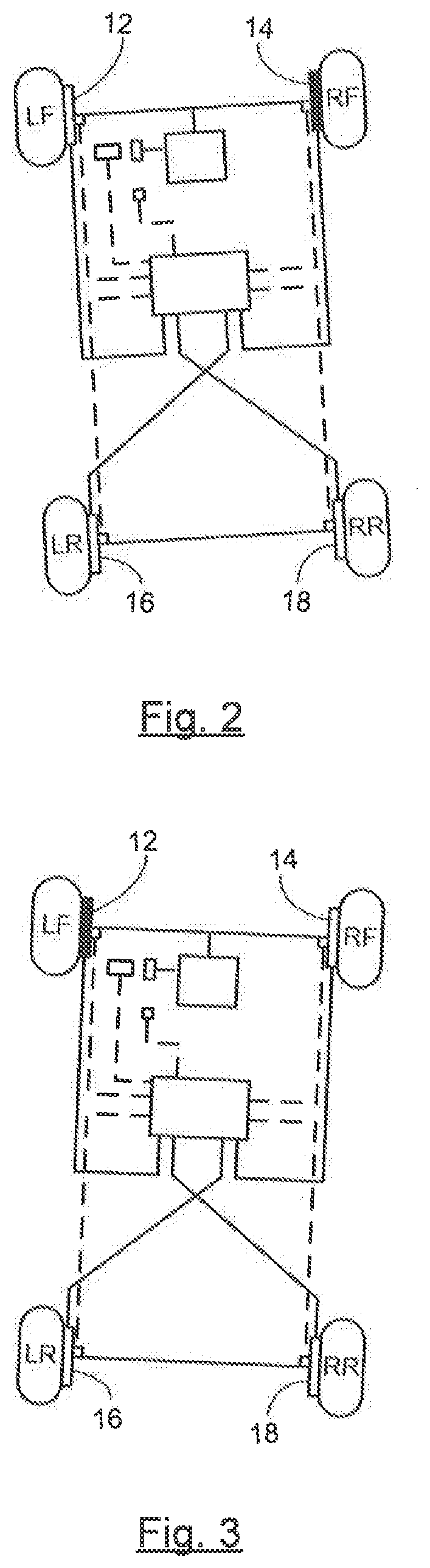
[0014]The vehicle is equipped with a plurality of vehicle wheels LF, RF, LR, and RR and a plurality of brake actuators—i.e., actuators and rotors—12, 14, 16, and 18 for braking an associated wheel. The plurality of brake actuators 12-18 are controlled by an electronic stability control unit (ESC) 20 that includes an electronic brake control module (EBCM) 21. EBCM 21 or similar module is a device that monitors and controls electronic braking functionality. The brake actuators 12-18 are not limited to any specific brake arrangement—e.g., a diagonal split arrangement or a front / rear split arrangement.

[0015]The ESC 20 receives inputs from various sensors including, but not limited...


PUM


Abstract

A stability control system of a vehicle utilizing an electronic control unit that minimizes rollback of a vehicle as a result of wheel slip immediately following a hill start assist operation. The electronic braking control module controls actuation and de-actuation of vehicle brakes on an inclined surface. Immediately following a hill start assist operation on the inclined surface after each wheel brake is de-actuated for allowing forward movement of the vehicle up the hill, a split-mu road surface condition is detected in response to sensing wheel slip for each of the wheels. The electronic control unit determines a respective undriven, or non-dominant driven, wheel having the highest coefficient of friction among the undriven, or less dominant driven wheels, as determined by the wheel speeds. The electronic braking control module actuates the vehicle brake of the undriven, or less dominant, driven wheels having the highest coefficient of friction relative to a tire/road surface interface for reducing rollback of the vehicle. The braking of the undriven, or less dominant, driven wheel is in addition to any standard stability control braking that may already be occurring.

Description

BACKGROUND OF THE INVENTION[0001]The present invention relates in general to stability control systems on split mu surfaces, and more specifically, stability control operations of a vehicle operating on a sloped surface after being at rest on the sloped surface.[0002]Many vehicle controls now include electronic stability controls that are used to maintain a stability of the vehicle particularly when the vehicle has stability issues during Hill Start Assist operations. Hill Start Assist functionality includes brake pressure trapping operations to implement hill start controls. In Hill Start operations, a vehicle is temporarily stopped on an incline such as at a stop sign, stop light, or stopped in traffic. Hill Start Assist operations are designed to ramp out brake pressure as a driver, or autonomous driving system, increases the throttle, such that all the pressure is removed when the driver has input what is believed to be enough propulsive torque to progress forward up the hill.[0...

Claims


Application Information

Patent Timeline
Patent Type & Authority Applications(United States)
IPC IPC(8): B60T8/175B60T8/171B60T8/1755B60T8/24
CPCB60T8/175B60T8/171B60T8/1755B60T2270/213B60T8/245B60T2201/06B60T2210/124B60T8/246B60T8/1761B60T8/24B60T8/32
Inventor HAWLEY, SHAWN
Owner ZF ACTIVE SAFETY US INC
Why Eureka
Try Eureka