

Elevator control apparatus, and elevator control method
A technology for control devices and elevators, which is applied in the field of elevator control devices, can solve problems such as rising costs, and achieve the effects of ensuring stability, reducing starting impact and rolling back
- Summary
- Abstract
- Description
- Claims
- Application Information
AI Technical Summary
Problems solved by technology
Method used
Image

Examples
Embodiment approach 1
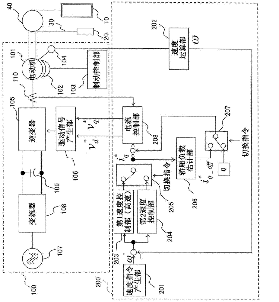
[0036] figure 1 It is a block diagram showing the elevator control device 200 according to Embodiment 1 of the present invention. in the figure 1 In the figure, the car 10, the counterweight 20, the suspension part 30, the drive sheave 40, the elevator drive part 100, and the control apparatus 200 of an elevator are shown in figure.
[0037]In addition, the elevator drive unit 100 has a motor 101, a brake 102, a brake control unit 103, a speed detector 104, an inverter 105, a drive signal generation unit 106, an AC power supply 107, an inverter 108, a smoothing capacitor 109, and a current detection unit. device 110.
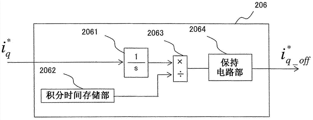
[0038] In addition, the elevator control device 200 has a speed command generation unit 201, a speed calculation unit 202, a first speed control unit 203, a second speed control unit 204, a first switching unit 205, a car load estimation unit 206, and a second switching unit. 207 and the current control unit 208.
[0039] The car 10 and the counterweight 20 ...
Embodiment approach 2
[0108] In Embodiment 1 above, the elevator control device 200 in which the first control system is configured to include the first speed control unit 203 and the second control system is configured to include the second speed control unit 204 has been described. On the other hand, in Embodiment 2 of the present invention, an elevator control device 200a will be described in which the speed command value is generated by the position control system included in the first control system during the start period, and the speed command value is generated by the second control system during the steady state period. The speed command generator 201 included in the control system outputs a speed command value.
[0109] Figure 4 It is a configuration diagram showing an elevator control device 200a according to Embodiment 2 of the present invention. Should Figure 4 The control device 200a of the elevator in the figure 1 The control device 200 of the elevator is different in that it pe...
Embodiment approach 3
[0133] In Embodiment 1 above, the elevator control device 200 in which the response speeds of the first speed control unit 203 and the second speed control unit 204 that are selectively switched at the time of elevator start-up is fixed has been described. On the other hand, in Embodiment 3 of this invention, the control apparatus 200b of an elevator which can continuously change the response speed of the 1st speed control part 203 whose response speed becomes high at the time of elevator startup is demonstrated.
[0134] Figure 5 It is a configuration diagram showing an elevator control device 200b according to Embodiment 3 of the present invention. Should Figure 5 The control device 200b of the elevator has a speed command generation part 201, a speed calculation part 202, a first speed control part 203, a second speed control part 204, a first switching part 205, a car load estimation part 206, a second switching part 207 , a current control unit 208 and a variable gain...
PUM
 Abstract
Description
Claims
Application Information