Self-aligning low load shear out joint

Pending Publication Date: 2021-03-04
THE BOEING CO
View PDF13 Cites 1 Cited by
  • Summary
  • Abstract
  • Description
  • Claims
  • Application Information

AI Technical Summary

Benefits of technology

The patent describes a self-aligning support for a flap that is designed to be easily attached to an aircraft. The support is made up of a fitting and rotating pins that connect the flap to the attachment support. The support can accommodate different directions of force and also has a fuse pin to prevent the pins from moving too much. The technical effect of this design is to provide a reliable and flexible attachment for flaps that can withstand high loads and accommodate changes in force direction.

Problems solved by technology

Furthermore, such tracks should not be the cause of an inadvertent mechanical jam which could lead to less than optimal performance of the flaps.
However, these fuse pins are typically sized for high deployment loads, resulting in correspondingly high fusing loads.
However, with certain arrangements of auxiliary supports, the typical deployment load can be an appreciable portion of the total load on the flap.
Therefore, the fusing loads may substantially impact the overall design of the flap and may be the principle sizing load case for the flap, adding considerable weight and cost to the flap and support structure.

Method used


Image

  • Self-aligning low load shear out joint
  • Self-aligning low load shear out joint
  • Self-aligning low load shear out joint

Examples


Embodiment Construction

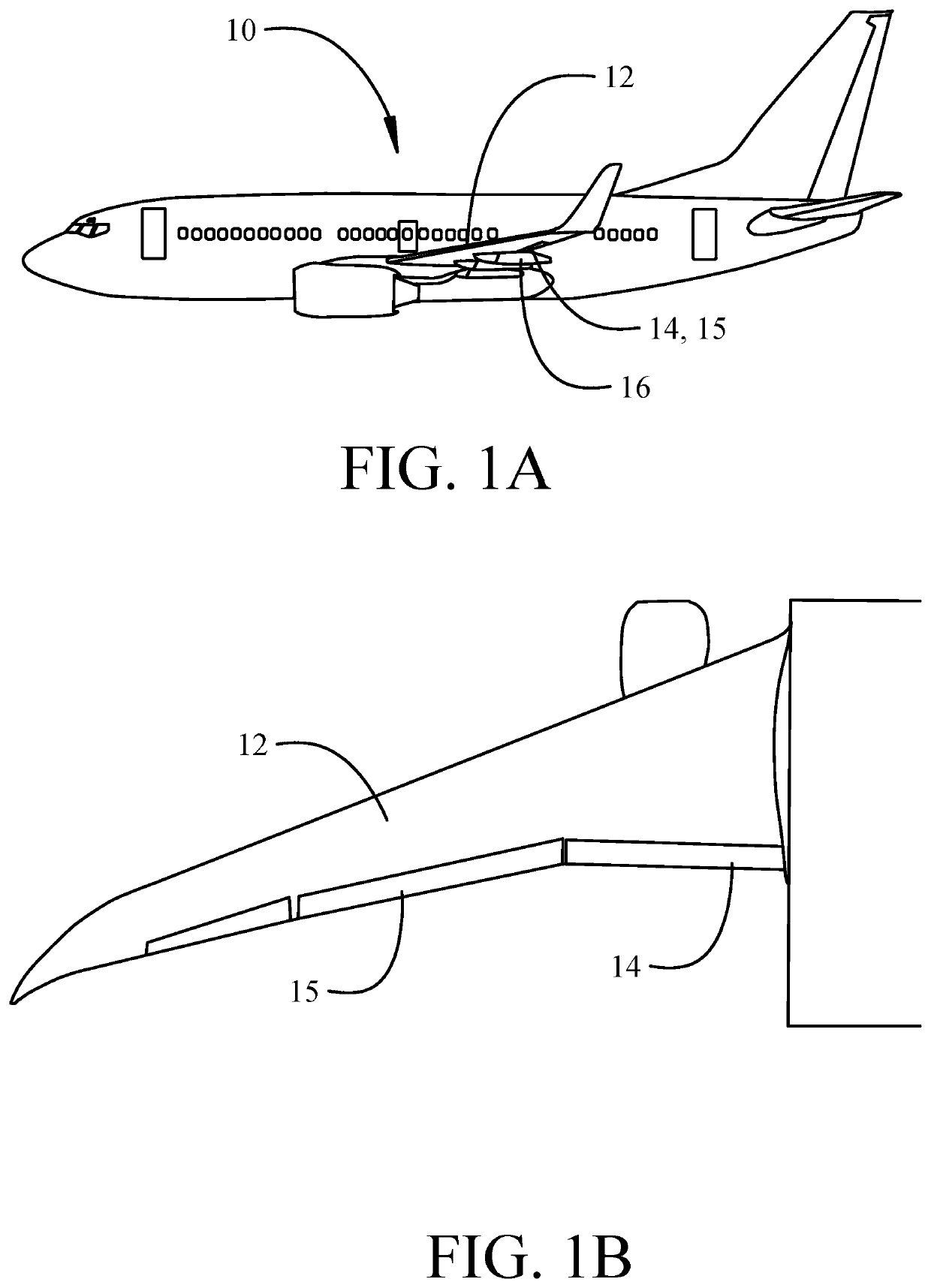
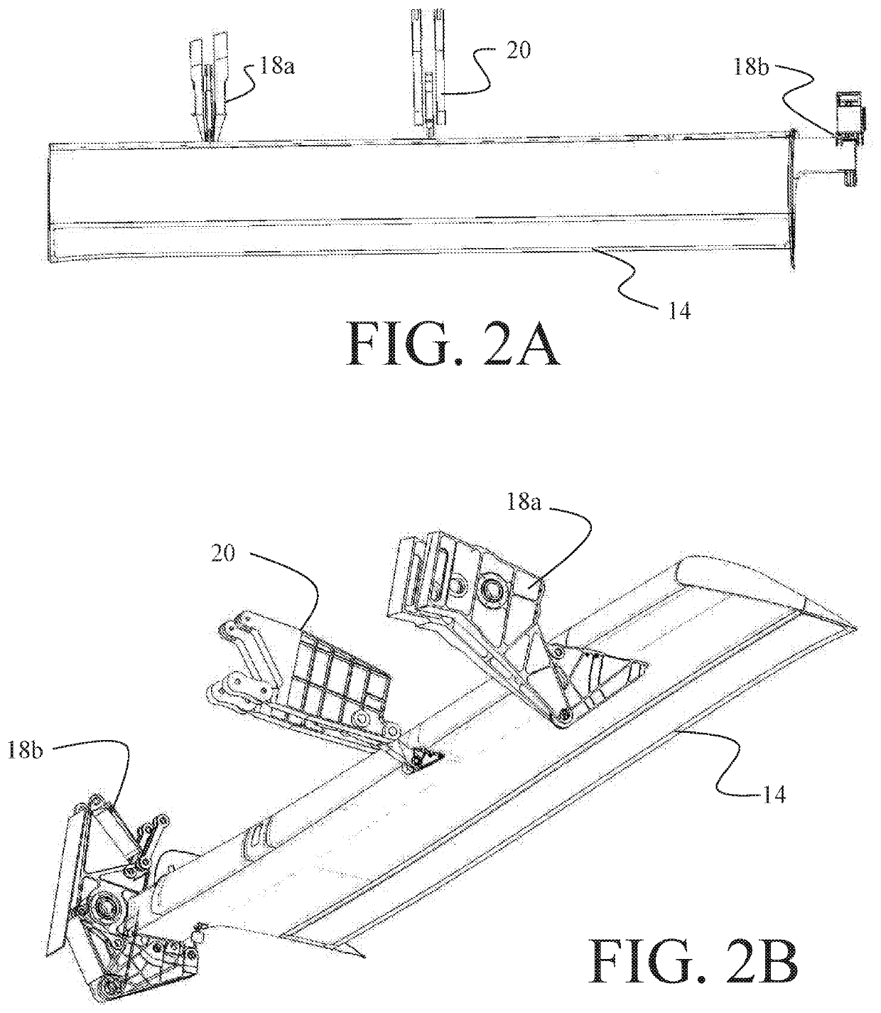
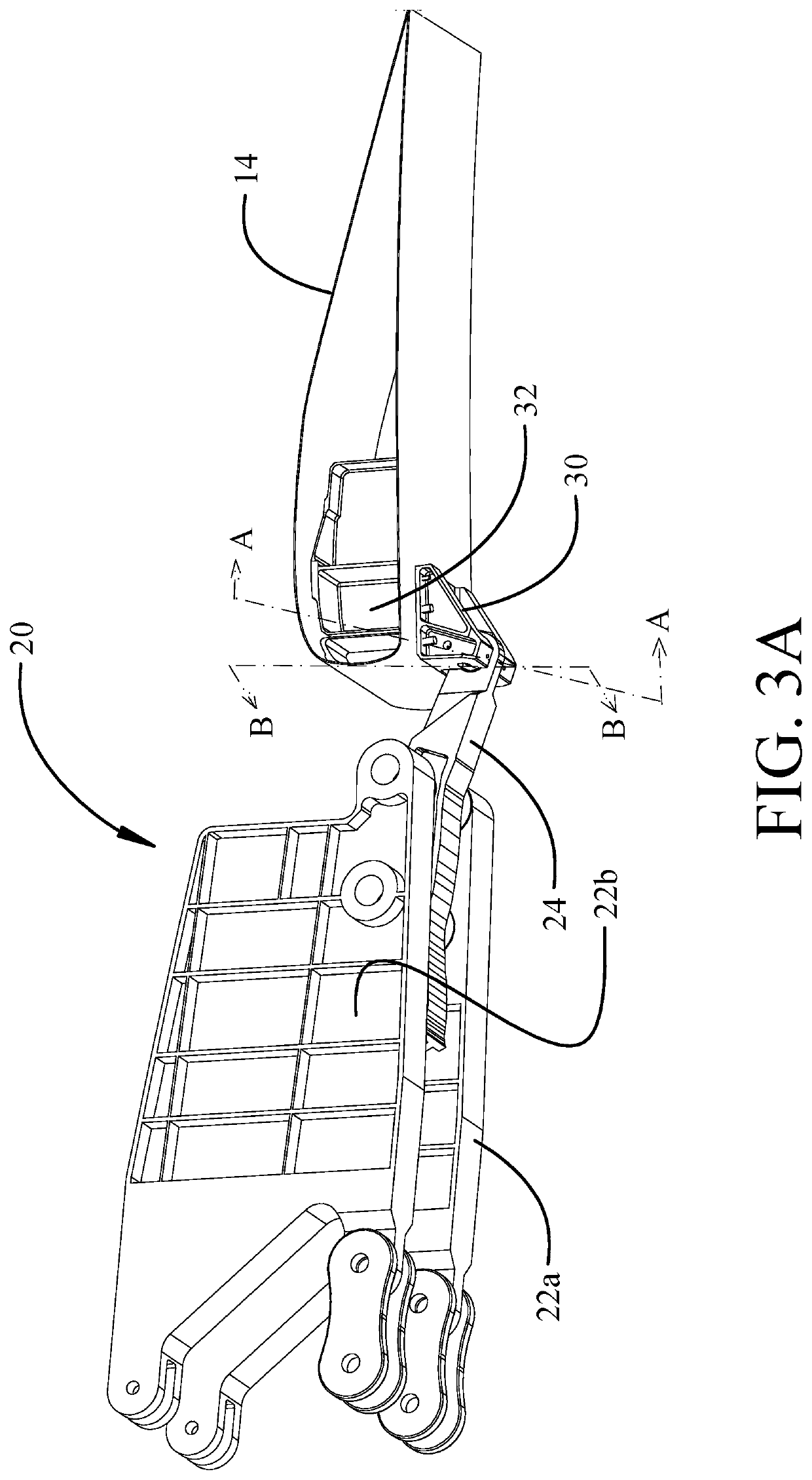
[0027]The implementations described herein provide a flap attachment fitting and a self-aligning fuse pin arrangement for an auxiliary flap support that overcomes the issues in the existing structures. While the example implementations described herein address an auxiliary flap support application, leading edge slats, primary flap tracks, auxiliary flap tracks, and deflection control tracks are also applicable configurations for use of the implementations. In the example implementations, an auxiliary track is coupled to the flap support attachment fitting with a primary load pin contained within slots in claws in the flap support attachment fitting. The primary load pin is prevented from translating from the nominal position in the slots by one or more key pins, which also serve as a low-load fuse pins, enabling substantial reduction in fusing load in the event that the auxiliary track becomes jammed, and the flaps are commanded to either retract or deploy. The claws, primary load p...


PUM


Abstract

A self-aligning support incorporates a support attachment fitting and a rotatable pin assembly having a primary load pin coupling the support attachment fitting to an attachment support, and inboard and outboard attachment claws engaged to end portions of the primary load pin. The rotatable pin assembly is configured to rotate relative to the support attachment fitting. At least one fuse pin extends through the primary load pin to limit translation of the primary load pin relative to the inboard and outboard claws.

Description

REFERENCE TO RELATED APPLICATIONS[0001]This application is copending with application Ser. No. ______ filed substantially concurrently herewith entitled LOW LOAD SHEAR OUT AUXILIARY SUPPORT JOINT and carrying attorney docket no. 19-1010-US-NP having a common assignee with the present application, the disclosure of which is incorporated herein by reference.BACKGROUND INFORMATIONField[0002]This disclosure relates generally to the field of aircraft flap systems and, more particularly to a flap deployment system having an auxiliary support with self-aligned fuse pins for jam mitigation.Background[0003]Aircraft employ flaps and leading edge slats which deploy to increase camber and chord of the wings for enhanced aerodynamic efficiency in take-off and landing. In modern flap configurations, one or more auxiliary flap supports or deflection control tracks may be used to balance loads or prevent excessive flap box deflection under load, such tracks should not inhibit the ability of the fla...

Claims


Application Information

Patent Timeline
IPC IPC(8): F16B19/00B64C9/20
CPCF16B19/00B64C9/02B64C9/20B64C9/16Y02T50/40F16D9/06F16C11/045Y10T403/32861
Inventor GRUNER, BRYAN J.HOMRICH, JOHN THOMAS B.
Owner THE BOEING CO
Why Eureka
Try Eureka