Housing and Electric Mower

Active Publication Date: 2021-03-11
KUBOTA LTD
View PDF8 Cites 0 Cited by
  • Summary
  • Abstract
  • Description
  • Claims
  • Application Information

AI Technical Summary

Benefits of technology

[0020]With the housing in which ventilation property and waterproof property are secured, the electric mower can maintain oper

Problems solved by technology

Working machine may be exposed to wind and rain, and receive jetted water, for example when it is washed.
At such a time,

Method used


Image

  • Housing and Electric Mower
  • Housing and Electric Mower
  • Housing and Electric Mower

Examples


Example

[0026][Basic Configuration of Electric Mower]

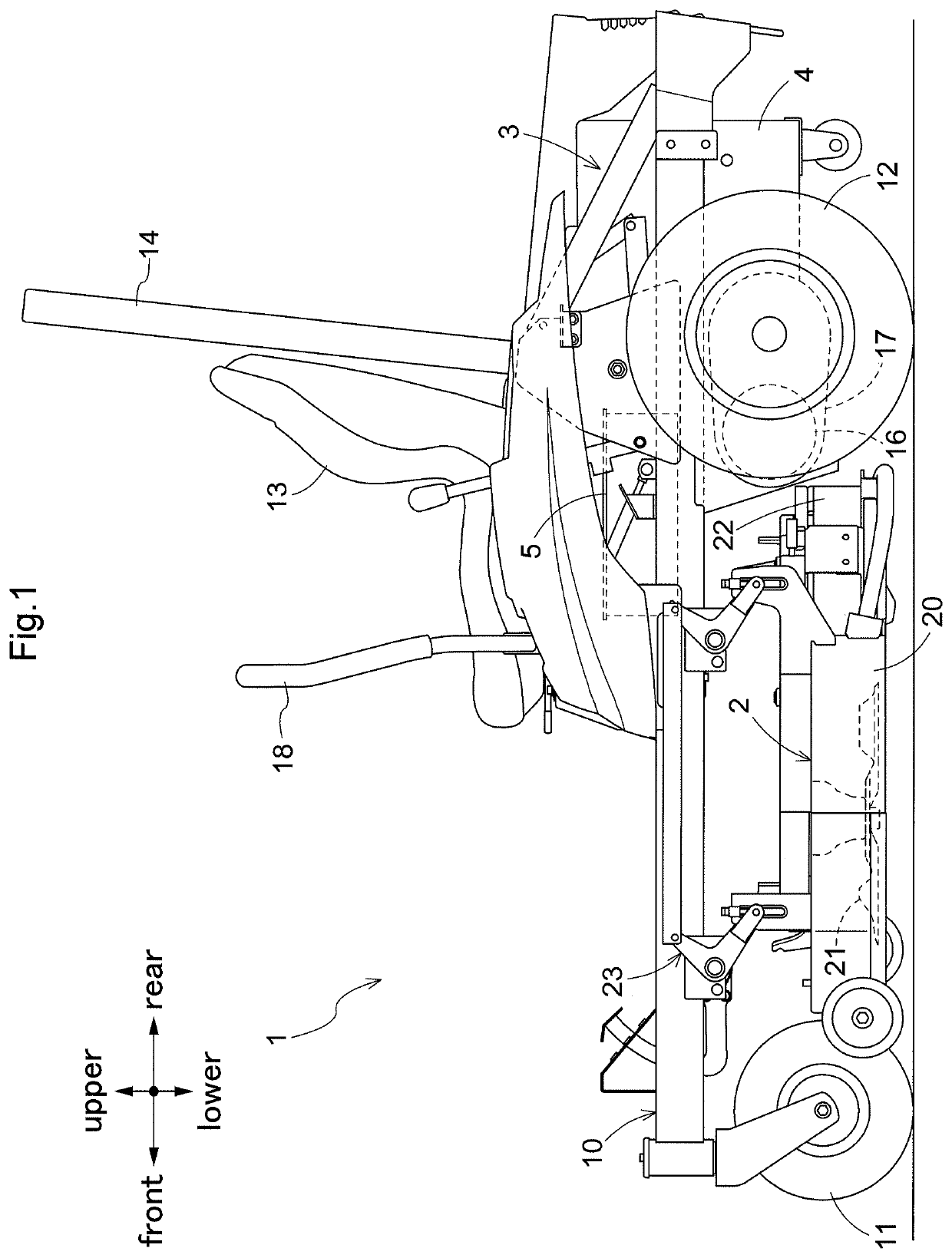
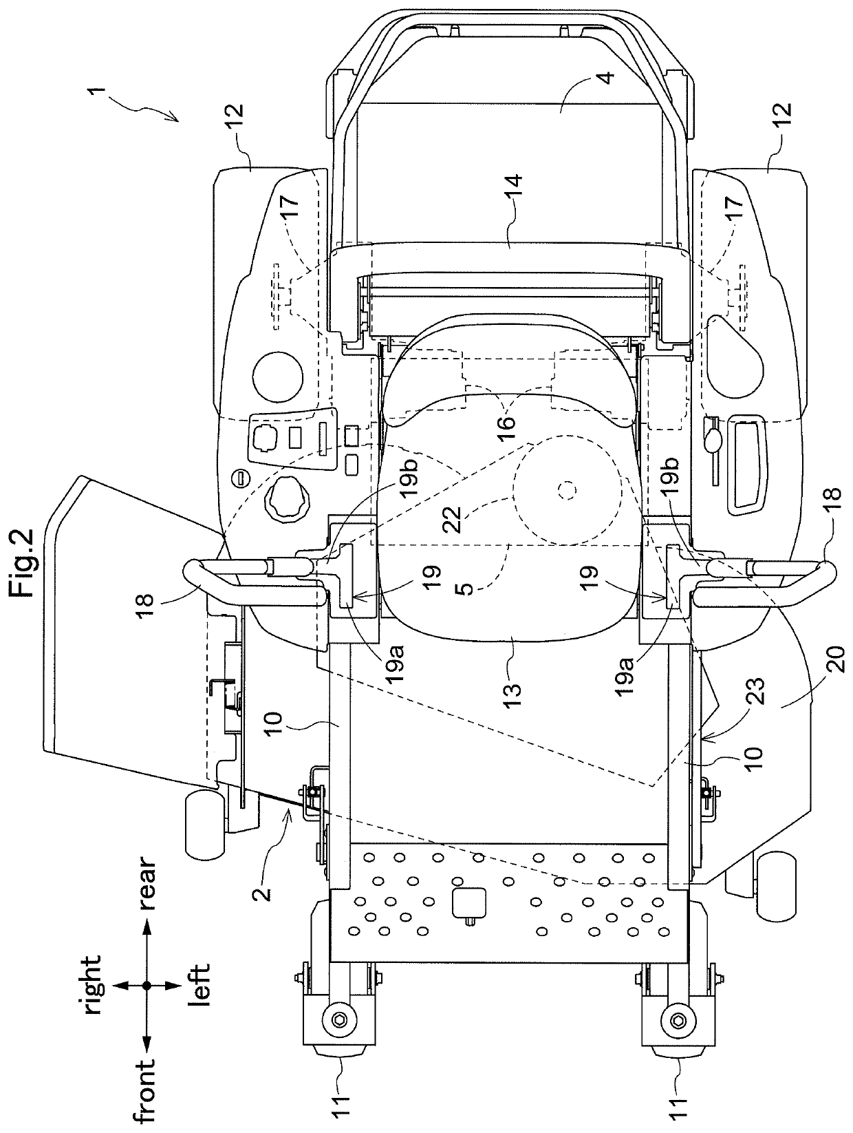
[0027]An embodiment of a work vehicle according to the present invention will be described. Unless otherwise specified, the term “front” means forward with respect to the front-rear direction of a vehicle body (traveling direction), and “rear” means rearward with respect to the front-rear direction of the vehicle body (traveling direction) herein. Further, the left-right direction or the lateral direction means the transverse direction of the vehicle body (vehicle body width direction) orthogonal to the front-rear direction of the vehicle body. “Upper” or “lower” is a positional relation with the vertical direction (perpendicular direction) of the vehicle body and means a relation to height above ground level.

[0028]In FIG. 1 and FIG. 2, an electric mower is shown as an example of work vehicle. The electric mower includes a vehicle body 1, a pair of right and left front wheels 11, 11, a pair of right and left rear wheels 12, 12, a mower un...


PUM


Abstract

A housing holding parts includes a plurality of outer circumferential plates connected with each other to form a first enclosed space, one or more of the outer circumferential plates having a total of two or more outer holes formed therein, and a gutter member connected to at least two outer circumferential plates, the gutter member having an inner hole formed therein, wherein a second enclosed space is formed by the outer circumferential plates and the gutter member, the outer holes communicate with the second enclosed space, and the inner hole is provided to be offset from each of the lines passing through each of the outer holes which are perpendicular to the outer circumferential plates in which the outer holes 8 are formed.

Description

CROSS-REFERENCE TO RELATED APPLICATION[0001]This claims priority to Japanese Patent Application No. 2019-163700 filed Sep. 9, 2019, the disclosure of which is hereby incorporated by reference in its entirety.TECHNICAL FILED[0002]The present invention relates to a housing mounted on a working machine and holding parts, and an electric mower equipped with the housing.BACKGROUND ART[0003]Working machines such as electric mowers are equipped with a housing holding various parts including electronic components and circuit boards. The housing has a space for holding parts therein, and for example has a rectangular parallelepiped shape made of six outer circumferential plates combined. As described in Patent Literature 1, ventilation needs to be provided for the housing in consideration of heat dissipation of parts and the like, and openings are formed in the outer circumferential plates.[0004]Working machine may be exposed to wind and rain, and receive jetted water, for example when it is...

Claims


Application Information

Patent Timeline
IPC IPC(8): A01D34/81A01D34/64A01D34/78
CPCA01D34/81A01D34/78A01D34/64A01D69/02H05K5/0214H05K7/1432
Inventor MATSUDA, KAZUAKIITO, HIROKAZU
Owner KUBOTA LTD
Why Eureka
Try Eureka