
Cleaner head for a vacuum cleaner

a vacuum cleaner and cleaner head technology, applied in the direction of suction cleaners, cleaning equipment, suction nozzles, etc., can solve the problems of reducing pick-up performance, increasing the torque of the agitator, and the failure of the agitator, so as to reduce the size of the housing and the overall footprint of the cleaner head, and facilitate maintenance and/or replacement. , the effect of simple maintenance and/or replacemen

Inactive Publication Date: 2021-03-11
DYSON TECH LTD
View PDF0 Cites 1 Cited by
  • Summary
  • Abstract
  • Description
  • Claims
  • Application Information

AI Technical Summary

Benefits of technology

The patent describes a cleaner head and agitator that can collect debris and remove it from a channel. The goal is to reduce friction and heat by only doing this operation once. The design also allows for more efficient removal of debris by having multiple points of contact with the debris removal members.

Problems solved by technology

This may lead to an increased torque on the agitator, and a sufficient build-up of debris may lead to failure of the agitator, and hence a reduced pick-up performance.
This can lead to the generation of excessive friction and heat due to repeated engagement of the cutting blade with debris during rotation of the agitator.

Method used


Image

  • Cleaner head for a vacuum cleaner
  • Cleaner head for a vacuum cleaner
  • Cleaner head for a vacuum cleaner

Examples


first embodiment

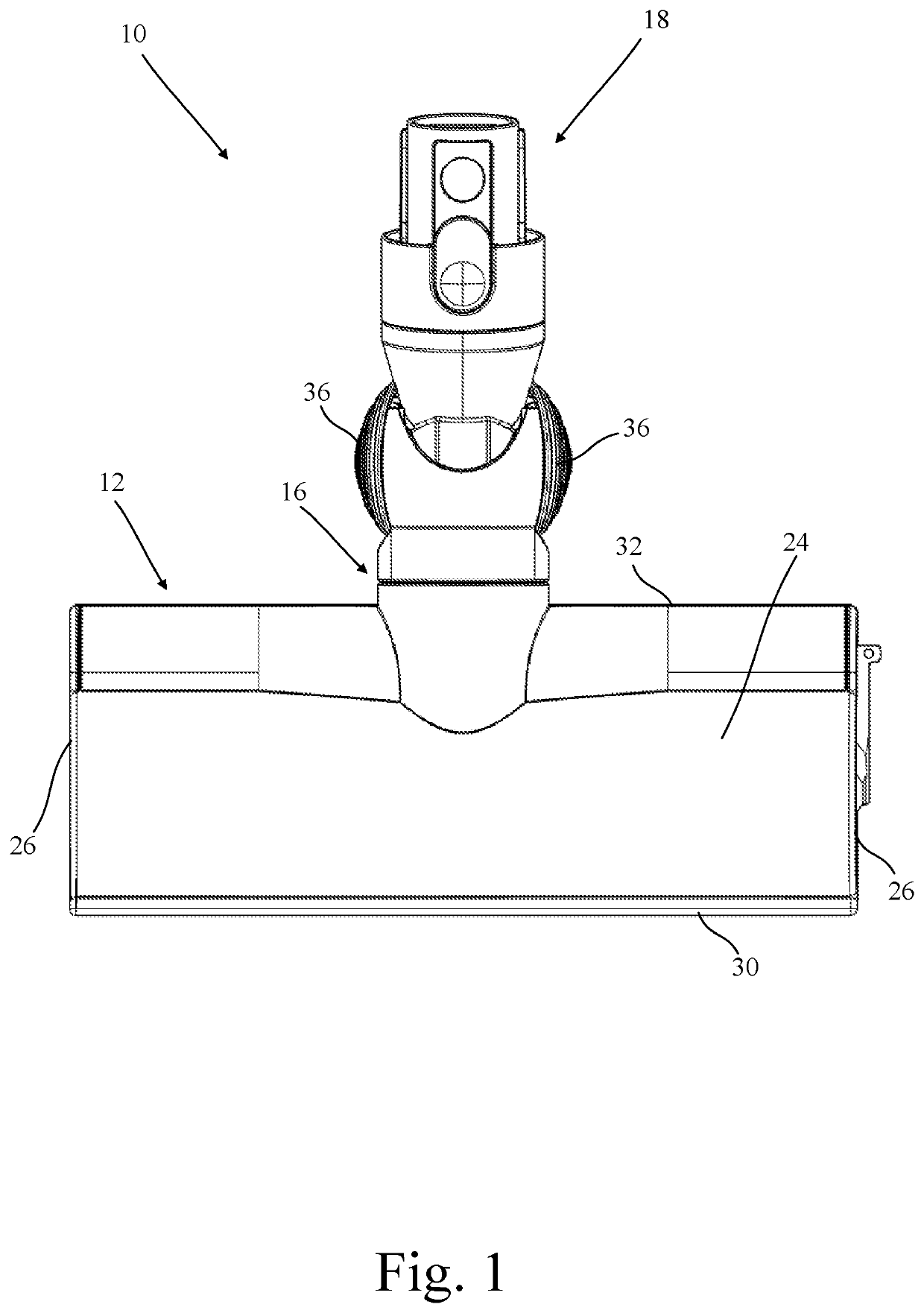
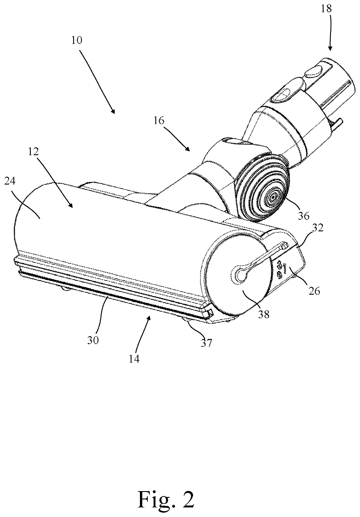
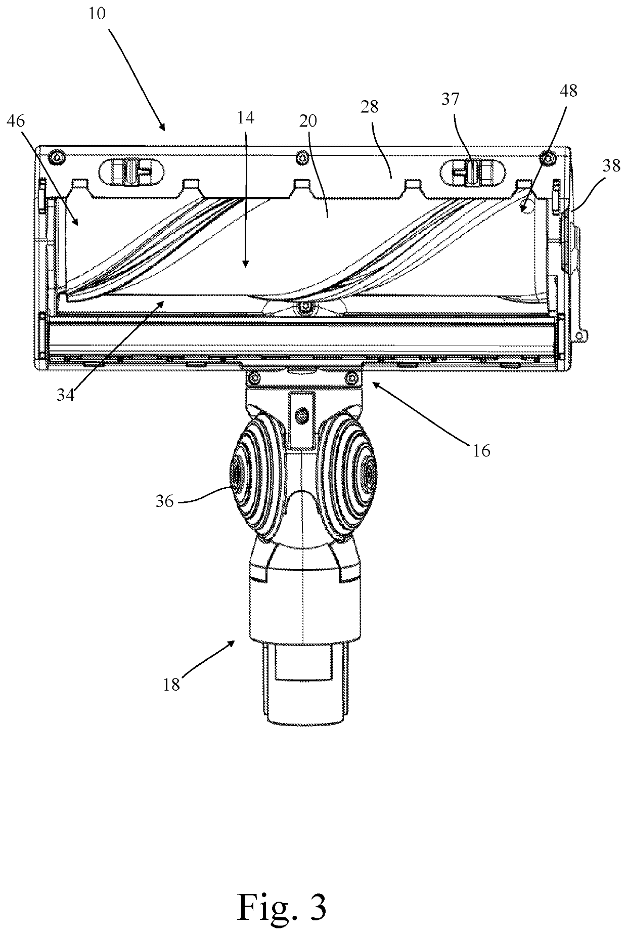
[0057]a cleaner head according to the present invention, generally designated 10, is shown in FIGS. 1-4.

[0058]The cleaner head 10 comprises a housing 12, a dirty air inlet 14, a dirty air outlet 16, a connection formation 18 extending from the dirty air outlet 16, an agitator in the form of a brush bar 20, a motor and drive unit 22, and a debris removal module 23.

[0059]The housing 12 has an upper wall 24, opposing side walls 26, a sole plate 28, a front wall 30, and a rear wall 32. Together the walls 24,26,28,30,32 define a substantially hollow internal chamber 34. An aperture formed in the sole plate 28 defines the dirty air inlet 14, whilst an aperture formed in the rear wall 30 defines the dirty air outlet 16. The connection formation 18 is generally tubular in form, and extends from the dirty air outlet 16 to enable the cleaner head 10 to be connected to a vacuum cleaner main body, either directly, or, for example, via an appropriate wand. The connection formation 18 has a first...

second embodiment

[0083]a cleaner head according to the first aspect of the present invention, generally designated 200, is shown in FIG. 17.

[0084]The second embodiment of the cleaner head 200 is substantially the same as the first embodiment of the cleaner head 10, and differs only in that the debris removal module 23 comprises an additional pair of debris removal members 202, 204, an additional connecting arm 206, an additional counterweight 208, and an additional spring (not shown), as seen in FIGS. 18 and 19. The additional components are structurally and functionally identical to the corresponding components of the first embodiment of the cleaner head 10, and differ only in that they are mounted on opposite sides of the cylindrical intermediate portion 68 and the pair of opposing arms 70 of the base 54.

[0085]Thus in the second embodiment there are two pairs of debris removal members 56,58,202,204 which are diametrically opposed upon the base 54, defining first 86 and second 210 debris collection...


PUM


Abstract

A cleaner head for a vacuum cleaner has a housing, an agitator rotatably mounted within the housing, and first and second debris removal members. The first debris removal member is movable relative to the second debris removal member between a first position in which the first) and second debris removal members are spaced apart to define a debris collection channel, and a second position in which the first and second debris removal members are contiguous or overlapping. Movement of the first debris removal member from the first position toward the second position removes debris from the debris collection channel, and movement of the first debris removal member is governed by rotation of the agitator.

Description

CROSS-REFERENCE TO RELATED APPLICATIONS[0001]This application is a national stage application under 35 USC 371 of International Application No. PCT / GB2018 / 053002, filed Oct. 17, 2018, which claims the priority of United Kingdom Application No. 1720699.6, filed Dec. 12, 2017, the entire contents of each of which are incorporated herein by reference.FIELD OF THE DISCLOSURE[0002]The present invention relates to a cleaner head for a vacuum cleaner.BACKGROUND OF THE DISCLOSURE[0003]Cleaner heads for vacuum cleaners typically comprise an agitator for agitating debris located upon a surface, and a dirty air inlet through which agitated debris can pass.[0004]During passage of agitated debris through the dirty air inlet, long strands of debris, for example hair or thread or the like, may become wrapped around the agitator or a mounting thereof. This may lead to an increased torque on the agitator, and a sufficient build-up of debris may lead to failure of the agitator, and hence a reduced pi...

Claims


Application Information

Patent Timeline
IPC IPC(8): A47L9/04A47L5/26A47L5/30
CPCA47L9/0477A47L9/0488A47L5/30A47L5/26A47L9/04A47L9/0461A47L9/0613
Inventor CARTER, THOMAS CLIFFORD
Owner DYSON TECH LTD
Learn More