Inverting thrombectomy apparatuses and methods of use

a thrombus and thrombosis technology, applied in the mechanical field, can solve the problems of insufficient or irregular blood flow through blood vessels, and achieve the effect of reducing the risk of thrombosis and thrombosis

Active Publication Date: 2021-03-11
STRYKER CORP
View PDF9 Cites 4 Cited by
  • Summary
  • Abstract
  • Description
  • Claims
  • Application Information

AI Technical Summary

Benefits of technology

[0008]In particular, described herein are apparatuses that may include an expandable funnel on the end of an inversion support catheter over which a flexible tube (e.g., tractor tube or simply tractor) rolls to invert. The flexible tube may be a knitted, or woven material. The flexible tube may generally have a first end coupled at a distal end region of a puller (which may be an elongate wire, tube, cannula, etc.), and the flexible tube may be arranged to invert over a distal end of the inversion support catheter at the funnel so that an external portion of the flexible tube extends proximally over the inversion support catheter as the internal (inverted) portion of the flexible tube is drawn into the funnel, compressing and removing fluid from the clot that is held by (e.g., grabbed by) the flexible tube, and pulling the inverted flexible tube into the inversion support catheter until the entire clot is captured, compressed and drawn into the outer catheter. The configuration of the apparatuses described herein are particularly well suited to grabbing and removing clot, and particularly large diameter clots, by using an inversion support catheter than includes an expandable funnel at the distal end. The collapsible / expandable funnel may configured to operate with the compressive forces applied by pulling the flexible tube into the inversion support catheter so that it inverts into the inversion support catheter, capturing the clot. The collapsible / expandable funnel may be configured to assume a fully expanded, locked (e.g., “jammed”) configuration when the flexible tube applies a laterally compressive force on the distal end face of the funnel. Further, the funnel may include openings (described herein as having a porous structure) through which fluid squeezed out of the clot may exit laterally out of the funnel as the clot is moved into the narrower-diameter lumen of the inversion support catheter and compresses the clot. For example, the openings through the collapsible / expandable funnel (which may be referred to herein as simply an expandable funnel) that permit fluid to laterally leave the funnel walls as the clot is compressed may also prevent clogging or jamming of the clot.
[0021]In general, the expandable funnels described herein may be configured to withstand a pulling force adequate to allow the flexible tube to invert, roll and pull a clot (even a very large-diameter clot) into the funnel, compress the clot (e.g., removing much of the fluid of the clot) and draw the compressed clot into the inversion support catheter body. For example, the expandable funnel may be configured to withstand greater than about 500 g of compressive force (e.g., greater than about 600 g, 700 g, 750 g, 800 g, 900 g, 1000 g, 1100 g, 1200 g, 1300 g, 1400 g, 1500 g, etc.) of compressive force without collapsing when the compressive force is directed axially (e.g., proximally). For example, the expandable funnel may be configured to withstand greater than 1200 g of compressive force without collapsing. In some variations the compressive force may result in a locking together or stacking of the funnel, particularly when the funnel is made of a woven, knitted or braided material. For example, with a woven funnel, the compressive force may jam the weave of the funnel material axially to increase the braid angle of the distal (wider) region increasing the column strength of the funnel.
[0050]In any of the expandable funnels described herein, the funnel surface may extend a relatively short distance from the distal end of the tines when the funnel is in the jammed and expanded configuration. For example the mesh forming the outer and inner surfaces, that may be secured to each other, but not to the tines, and the mesh may extend distally of the tines in the expanded configured to more than 5 mm or less (e.g., 4 mm or less, 3 mm or less, 2 mm or less, 1 mm or less, etc.) from a distal end of the plurality of tines when the expandable funnel is expanded to the jammed configuration. For example, the funnel surface may extend 1 mm or less from a distal end of the plurality of tines when the expandable funnel is expanded to the jammed configuration.
[0061]Any of the inversion support catheters described herein may include a stop at a proximal end region of the inversion support catheter that is configured to prevent the flexible tube of knitted or woven material from extending over the outer surface of the inversion support catheter proximally past the stop. This may be particularly useful when a flexible tube installed (e.g., by a user) over an inversion support catheter, and inserted into a delivery catheter; even with a tear-away sleeve preventing the flexible tube (which may be a knitted tube, for example) from pushing proximally as the inversion support catheter and flexible tube is pushed distally into the delivery catheter.

Problems solved by technology

Many vascular problems stem from insufficient blood flow through blood vessels.
One causes of insufficient or irregular blood flow is a blockage within a blood vessel referred to as a blood clot, or thrombus.

Method used


Image

  • Inverting thrombectomy apparatuses and methods of use
  • Inverting thrombectomy apparatuses and methods of use
  • Inverting thrombectomy apparatuses and methods of use

Examples


Embodiment Construction

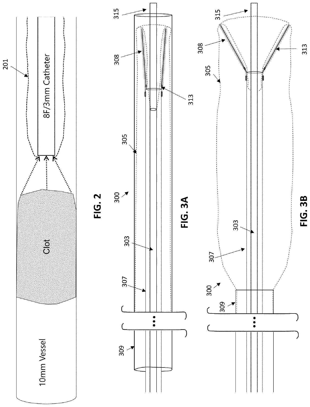
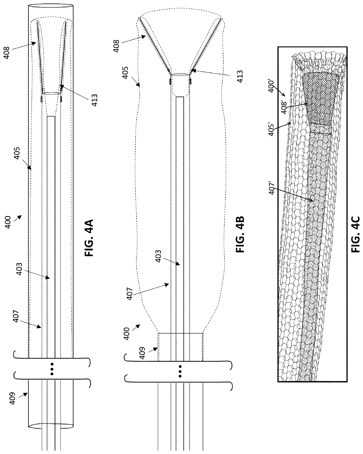
[0110]In general, described herein are inverting tube apparatuses (e.g., devices and systems) that are particularly well suited for removal of larger-diameter clots and / or atheromas. Any of the inverting tube apparatuses may include an inversion support catheter having an elongate and flexible body with an expandable funnel at a distal end of the body, and also a flexible tube that rolls and inverts over the inversion support catheter including the expandable funnel when the flexible tube is pulled proximally into the inversion support catheter. The inversion support catheters may be used with or without a flexible tube.

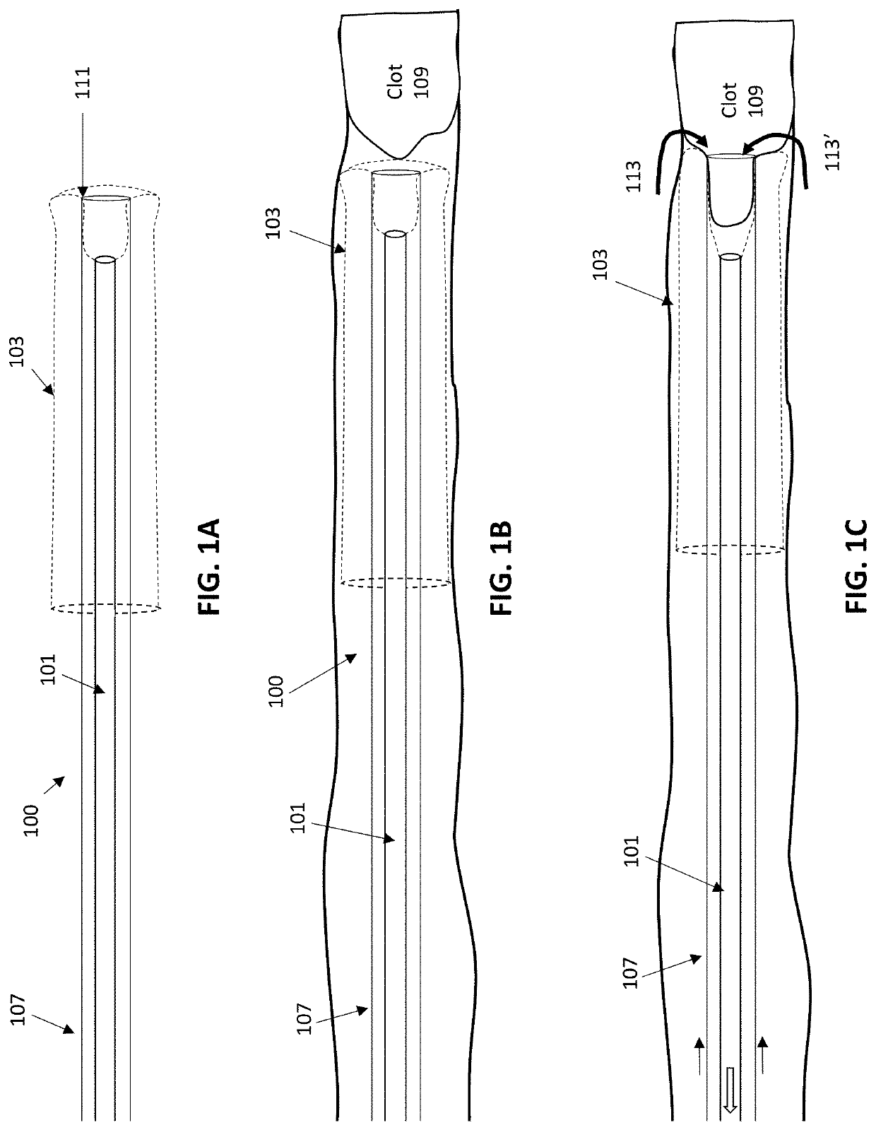
[0111]Previously described mechanical inverting tube apparatuses (also referred to as “mechanical thrombectomy apparatuses”) were configured to remove clot effectively, as shown in FIGS. 1A-1C. The apparatuses and methods of using them described herein may particularly effective for use with the peripheral vasculature, including for use with relatively larger outer d...


PUM


Abstract

Described herein are methods using mechanical inverting tube apparatuses to remove clot (e.g., thrombectomy), the apparatuses including an inversion support catheter having an expandable funnel-shaped distal end, and a flexible tube that can be continuously rolled over the funnel-shaped distal end and invert into the inner lumen of the inversion support catheter.

Description

CROSS REFERENCE TO RELATED APPLICATIONS[0001]The present application is a continuation of PCT / US2019 / 050467, having an international filing date of Sep. 10, 2019, which claims priority to U.S. provisional patent application No. 62 / 729,276, titled “INVERTING THROMBECTOMY APPARATUSES FOR REMOVAL OF LARGE CLOTS,” filed on Sep. 10, 2018, which are herein incorporated by reference in its entirety.INCORPORATION BY REFERENCE[0002]All publications and patent applications mentioned in this specification are herein incorporated by reference in their entirety to the same extent as if each individual publication or patent application was specifically and individually indicated to be incorporated by reference.FIELD[0003]The apparatuses and methods described herein relate to mechanical removal of objects from within a body. In particular, described herein are mechanical thrombectomy apparatuses and methods.BACKGROUND[0004]Many vascular problems stem from insufficient blood flow through blood vess...

Claims


Application Information

Patent Timeline
Patent Type & Authority Applications(United States)
IPC IPC(8): A61B17/22A61M25/00A61M25/06A61B17/3207
CPCA61B17/22031A61M25/0082A61B17/32075A61M25/0043A61M25/0662A61M25/0074A61B17/221A61B17/320725A61B2017/2215A61B2017/320008A61B2017/3435
Inventor WALLACE, MICHAEL P.VAN, CLIFFORDLEGUIDLEGUID, ROYGREENHALGH, E. SKOTTTANG, WINNIE
Owner STRYKER CORP
Why Eureka
Try Eureka