Rotor blade monitoring system

a monitoring system and rotor blade technology, applied in the field of rotor blades, can solve the problems of in-situ inspection of wind turbine blades, cost and time-consuming, and difficulty in planning and performing inspections,

Pending Publication Date: 2021-03-11
SIEMENS GAMESA RENEWABLE ENERGY AS
View PDF8 Cites 2 Cited by
  • Summary
  • Abstract
  • Description
  • Claims
  • Application Information

AI Technical Summary

Benefits of technology

[0010]The camera may be mounted directly or indirectly at a mounting portion of the inner surface, for example by gluing a mounting face of the camera or a mounting face of a frame at which the camera is mounted to the mounting portion of the inner surface. The camera may also be bolted to the inside of the rotor blade or may be mounted by other means. Thereby, simple monitoring of the structural state of the blade may be enabled.
[0012]Other embodiments of the present invention may not require a light source, since light from the environment may enter the inside of the rotor blade, for example in cases where the rotor blade wall is at least partly transparent. However, to more accurately control the brightness, the light source may be advantageous to accurately adjust brightness of the illuminated portion of the inner surface and / or adjust an image acquisition time of the camera to acquire at least one image. Using for example a control module or the like, the at least one light source may be controllable regarding switching on and off the light source and / or also regarding adjusting the brightness of the light source or the intensity of the light source. For example, a control module may be adapted to control the light source to switch the light source on only if acquiring at least one image is desired for monitoring the rotor blade. For example, at least one image may be taken on a regular time basis, such as daily, every two days, every week, three times a month or yearly, for example. During these periods of image acquisitions, the light source may be controlled to be switched on. The illumination light may comprise at least visible light (for example from about 300 nm to about 800 nm) and / or may at least comprise one or more wavelength ranges within the visible light spectrum. Further, the illumination light may comprise or may not comprise infrared light (or at least some wavelength range of the infrared spectrum) and / or ultraviolet light or ultraviolet wavelength ranges. Having an appropriate illumination by the light source may improve the image quality.
[0015]When an adhesive is used, the shape of the outer surface (in particular forming an airfoil) of the rotor blade may not be altered or effected. Thereby, the aerodynamic property of the rotor blade may be unchanged. The adhesive may for example be or comprise a polymer resin which has been hardened, thereby forming a cross-linked polymer. Also, the rotor blade wall (having the inner surface and the outer airfoil) may be manufactured from a polymer which has been cross-linked. Other manufacturing materials and methods are possible. Thereby, mounting the camera and / or the light source at conventionally utilized rotor blade materials may be enabled.
[0016]According to an embodiment of the present invention, the at least one camera and / or the at least one light source is mounted on at least one frame that is mounted on the inner surface. The frame may enable to properly adjust the orientation of the camera and / or the light source such that the light source illuminates a region of the inner surface which is also in the viewing range of the camera. Further, the frame may enable to properly adjust the orientation and positioning of the camera and / or the light source such that the camera does not shadow the illumination light, is not in the illumination light path. The frame may have mounted thereon one camera, two cameras, three cameras or even more cameras and one light source, two light sources, three light sources or even more light sources.
[0017]According to an embodiment of the present invention, the frame has a mounting surface which is fit, in particular complementary, to a shape of the mounting portion of the inner surface. When the mounting surface of the frame is complementary to the shape of the mounting portion of the inner surface, the mounting surface may in a simple manner be glued to the mounting portion of the inner surface, thereby simplifying mounting the frame to the inside of the rotor blade. Providing the frame may allow to utilize conventionally available cameras and light sources without requiring the cameras and the light sources to have particularly shaped mounting surfaces, since the frame may serve as an adaptor. Thereby, costs may be reduced. The frame may be made of any material, such as a polymer, a metal, wood, any plastic, any thermosetting material, or the like. In particular, differently shaped frames regarding their mounting surface may be utilized having respective mounting surfaces which are complementary to different mounting portions of the inner surface, for example along the longitudinal direction of the rotor blade.
[0022]Providing at least one image acquisition unit may simplify the construction and reduce costs. Inside the rotor blade, one image acquisition unit may be mounted on for example a back side of a luv outer surface of the rotor blade and another image acquisition unit may be oppositely mounted inside the rotor blade at a back side of a lee outer surface of the rotor blade. Thereby, a set of acquisition units is formed. Several sets of image acquisition units may be mounted inside the rotor blade for example spaced apart along a longitudinal direction of the rotor blade.

Problems solved by technology

The rotor blades may be subject to wear during operation such that they deteriorate over prolonged operation time.
In-situ inspection of blades on wind turbines however is currently costly and time-consuming.
Furthermore, it may be weather-dependent and often the wind turbines are situated in hard-to-access sites in remote areas or offshore installations, making it difficult to plan and perform inspections.
Additionally, the rotor blades nowadays are relatively large and expensive components of wind turbines.
Thus, a lengthy structural repair involving stopped energy production or blade loss due to structural damage may involve major disadvantages.

Method used


Image

  • Rotor blade monitoring system
  • Rotor blade monitoring system
  • Rotor blade monitoring system

Examples


Embodiment Construction

[0046]The illustration in the drawings is in schematic form. It is noted that in different figures, similar or identical elements are provided with the same reference signs or with reference signs, which are different from the corresponding reference signs only within the first digit.

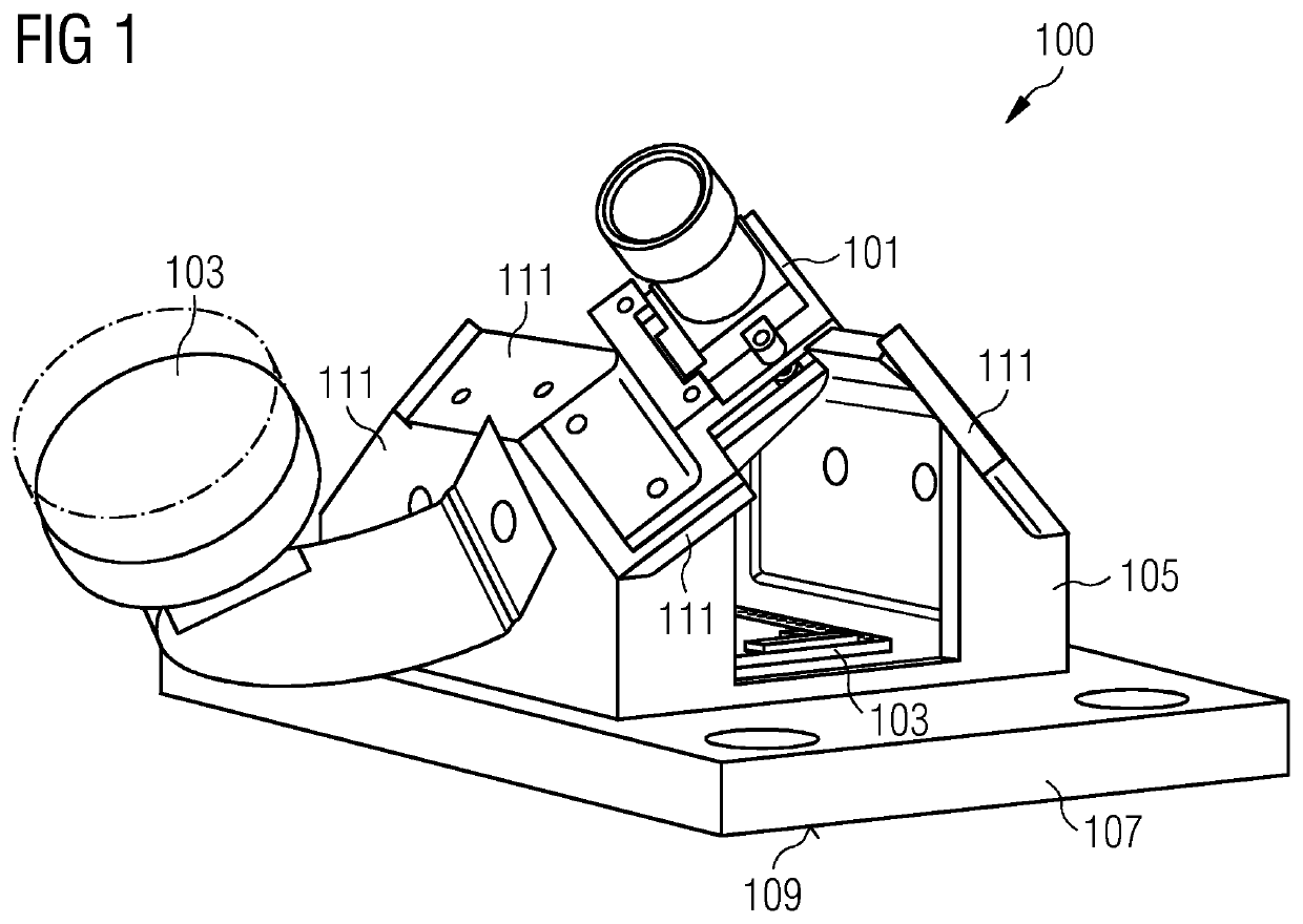
[0047]According to an embodiment of the present invention, multiple, permanent mounted camera sensors are regularly (e.g. at regular time intervals) taking pictures covering the full internal surface of the rotor blade from the root start to the end of the web start. The camera sensors may be collected in units together with a light source, for example as is illustrated in a schematic form in FIG. 1.

[0048]Thereby, FIG. 1 illustrates an image acquisition unit 100 that may be installed inside a rotor blade according to an embodiment of the present invention. Thereby, the image acquisition unit 100 comprises an assembly of at least one camera 101, at least one light source 103 and a mounting frame 105 at w...


PUM


Abstract

Provided is a rotor blade for a wind turbine, including: at least one camera mounted inside the rotor blade and adapted to acquire an image of a portion of an inner surface of the rotor blade.

Description

CROSS-REFERENCE TO RELATED APPLICATIONS[0001]This application claims priority to PCT Application No. PCT / EP2019 / 053760, having a filing date of Feb. 15, 2019, which is based off of EP Application No. 18163345.4, having a filing date of Mar. 22, 2018, the entire contents both of which are hereby incorporated by reference.FIELD OF TECHNOLOGY[0002]The following relates to a rotor blade for a wind turbine, a rotor blade monitoring system, a wind turbine and further to a method of monitoring a structural state of a rotor blade of a wind turbine.BACKGROUND[0003]A wind turbine may comprise a rotation shaft with a hub at which plural rotor blades are mounted. The rotation shaft may mechanically be coupled with a rotor of a generator to generate electric energy upon rotation of the hub to which the rotor blades are connected. The rotor blades may be subject to wear during operation such that they deteriorate over prolonged operation time.[0004]Therefore, monitoring the structural state or st...

Claims


Application Information

Patent Timeline
Patent Type & Authority Applications(United States)
IPC IPC(8): F03D17/00H04N5/225G06K9/46G06K9/20
CPCF03D17/00H04N5/2253F05B2270/8041G06K9/2018F05B2260/80G06K9/4671H04N23/54
Inventor GIROLAMO, DONATOORLOWITZ, ESBENSTEVANOVIC, NEVENA
Owner SIEMENS GAMESA RENEWABLE ENERGY AS
Why Eureka
Try Eureka