
Multi Range Radar System

Active Publication Date: 2021-03-11
IBM CORP
View PDF0 Cites 0 Cited by
  • Summary
  • Abstract
  • Description
  • Claims
  • Application Information

AI Technical Summary

Benefits of technology

This patent describes a method for determining the range of an object using two modulated continuous waves. The first wave is transmitted to the object, and a second wave is generated at a specific time. The received first wave is then mixed with the second wave to produce a beat signal, which is used to determine the range of the object. This method can provide accurate and efficient results in determining the range of an object from a known location.

Problems solved by technology

Drawbacks of such approaches, however, are that wider bandwidths and faster sweep times limit the number of devices that can be used simultaneously due to the need for extra computation, power consumption, and the use of state-of-art hardware.
Mid- and long range radar systems pose additional challenges, as the F-beat is high and therefore requires more computation.
However, this results in slower than possible radar readings.

Method used


Image

  • Multi Range Radar System
  • Multi Range Radar System
  • Multi Range Radar System

Examples


Embodiment Construction

[0014]The word “exemplary” is used herein to mean “serving as an example, instance, or illustration.” Any embodiment described herein as “exemplary” is not necessarily to be construed as preferred or advantageous over other embodiments. All of the embodiments described in this Detailed Description are exemplary embodiments provided to enable persons skilled in the art to make or use the invention and not to limit the scope of the invention which is defined by the claims.

[0015]The systems and methods described herein may be used in conjunction with radar systems that are capable of detecting objects at different ranges. One main idea thereof is to artificially increase a distance between the object being detected and the radar system. Based on this, a sufficient frequency resolution may be obtained for short-range detection of the object or even for optimization of the radar for a specific range. Also, the distance between the object being detected and the radar system may be artific...


PUM


Abstract

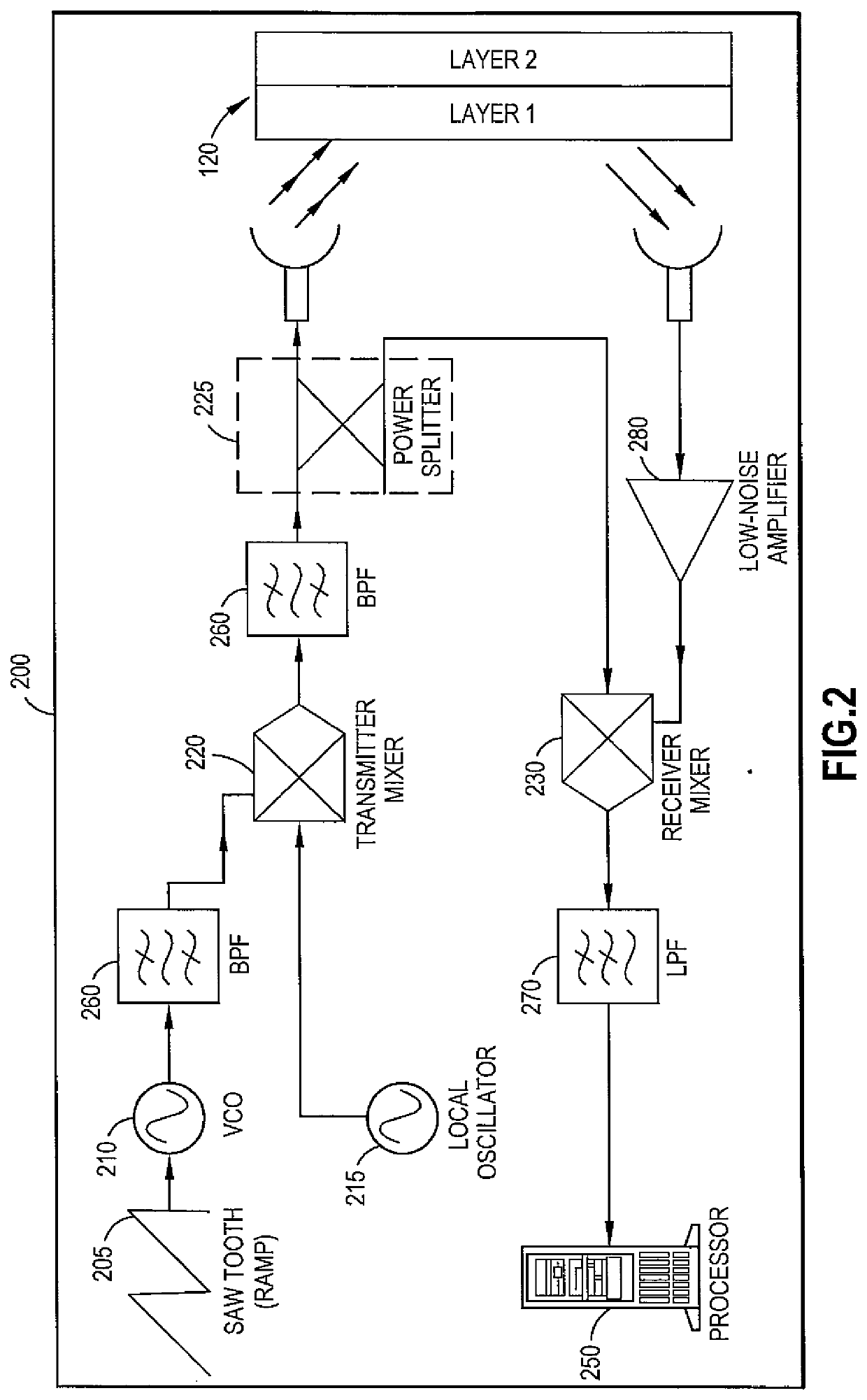
A method includes generating a first modulated continuous wave from a generating location; transmitting the first modulated continuous wave to an object positioned at a distance from the generating location; generating a second modulated continuous wave from the generating location, wherein the second modulated continuous wave is generated at a predetermined time that is different from a predetermined time at which the first modulated continuous wave is generated; receiving, at a mixer, the first modulated continuous wave from the object; receiving, at the mixer, the second modulated continuous wave from the generating location; mixing the received first modulated continuous wave with the second modulated continuous wave to produce a beat signal to determine a range of the object from the generating location; and outputting the determined range of the object from the generating location.

Description

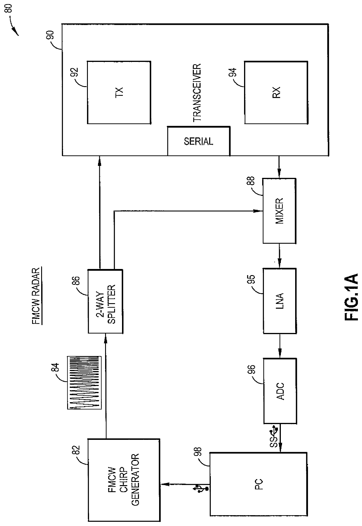
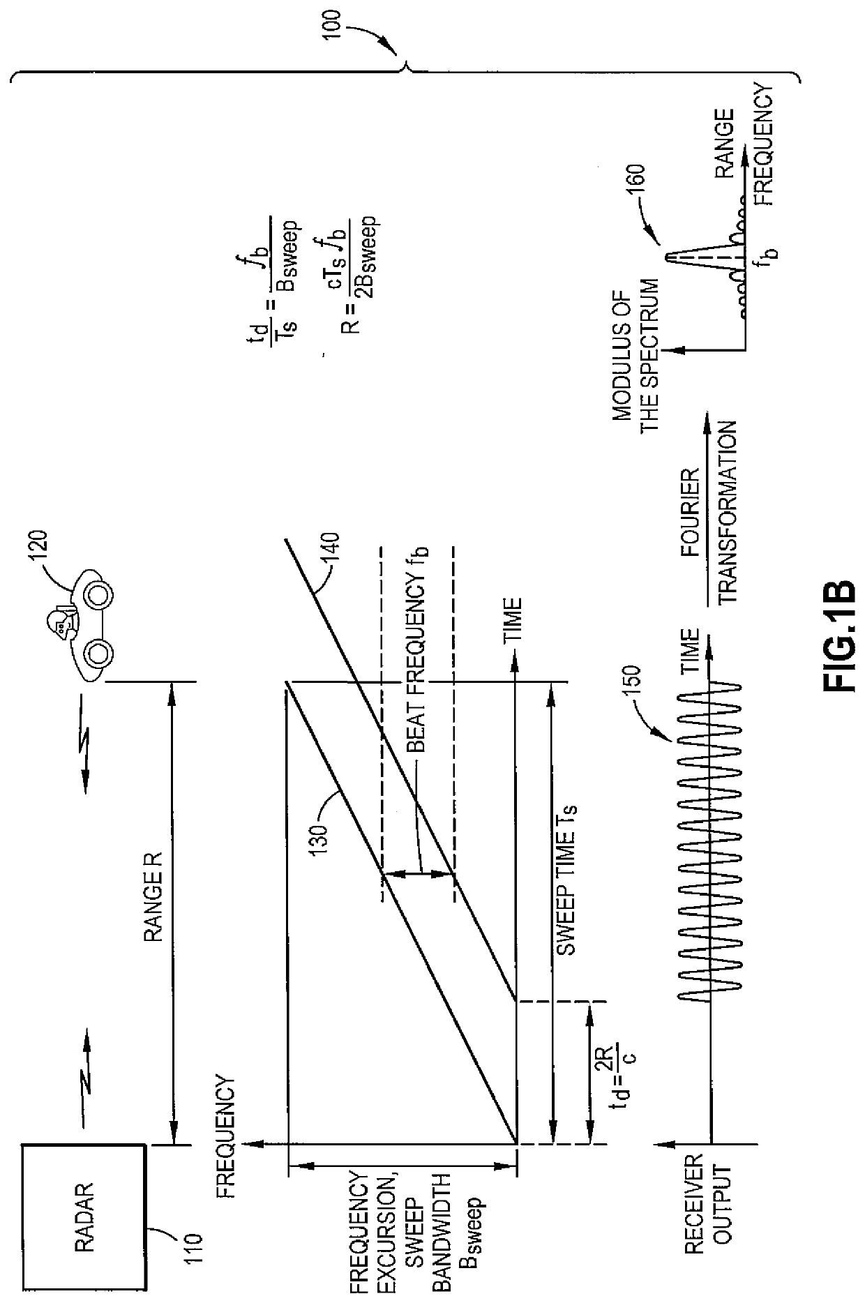
BACKGROUND[0001]The exemplary embodiments described herein relate generally to radar systems and, more specifically, to a radar system capable of detecting an object at different ranges.[0002]A state of the art radar system generally uses a Frequency Modulated Continuous Wave (FMCW) generator. In such a system, a waveform is transmitted, and a received signal is mixed with the transmitted signal. The system analyzes the frequency spectrum, with each peak of the spectrum representing a frequency difference (F-beat) and therefore the distance of the object from the transceiver. This system and its associated methods find use in mid- and long-range radar applications where the distance is substantial and therefore the frequency of the received signal is clear and accurate. In such a system, range resolution is defined by the bandwidth used, which also defines the minimum detectability of an object.[0003]Radar systems have been developed for autonomous driving and for other applications...

Claims


Application Information

Patent Timeline
IPC IPC(8): G01S13/34
CPCG01S13/347G01S13/343
Inventor TZADOK, ASAF
Owner IBM CORP
Learn More