

Rolling mill, and method for setting rolling mill
a technology of rolling mill and rolling mill, which is applied in the field of rolling mill, can solve the problems of difficult to directly measure such a thrust force, and achieve the effect of suppressing the occurrence of zigzagging and camber of workpieces and the thrust for
- Summary
- Abstract
- Description
- Claims
- Application Information
AI Technical Summary
Benefits of technology
Problems solved by technology
Method used
Image

Examples
first embodiment
2. First Embodiment
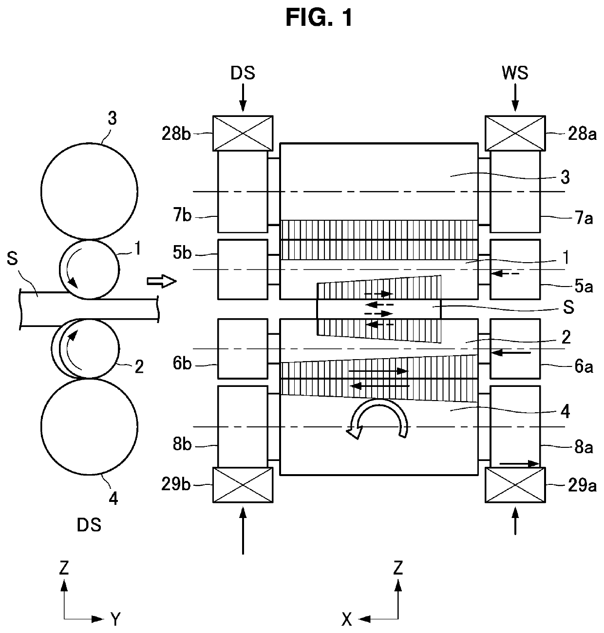
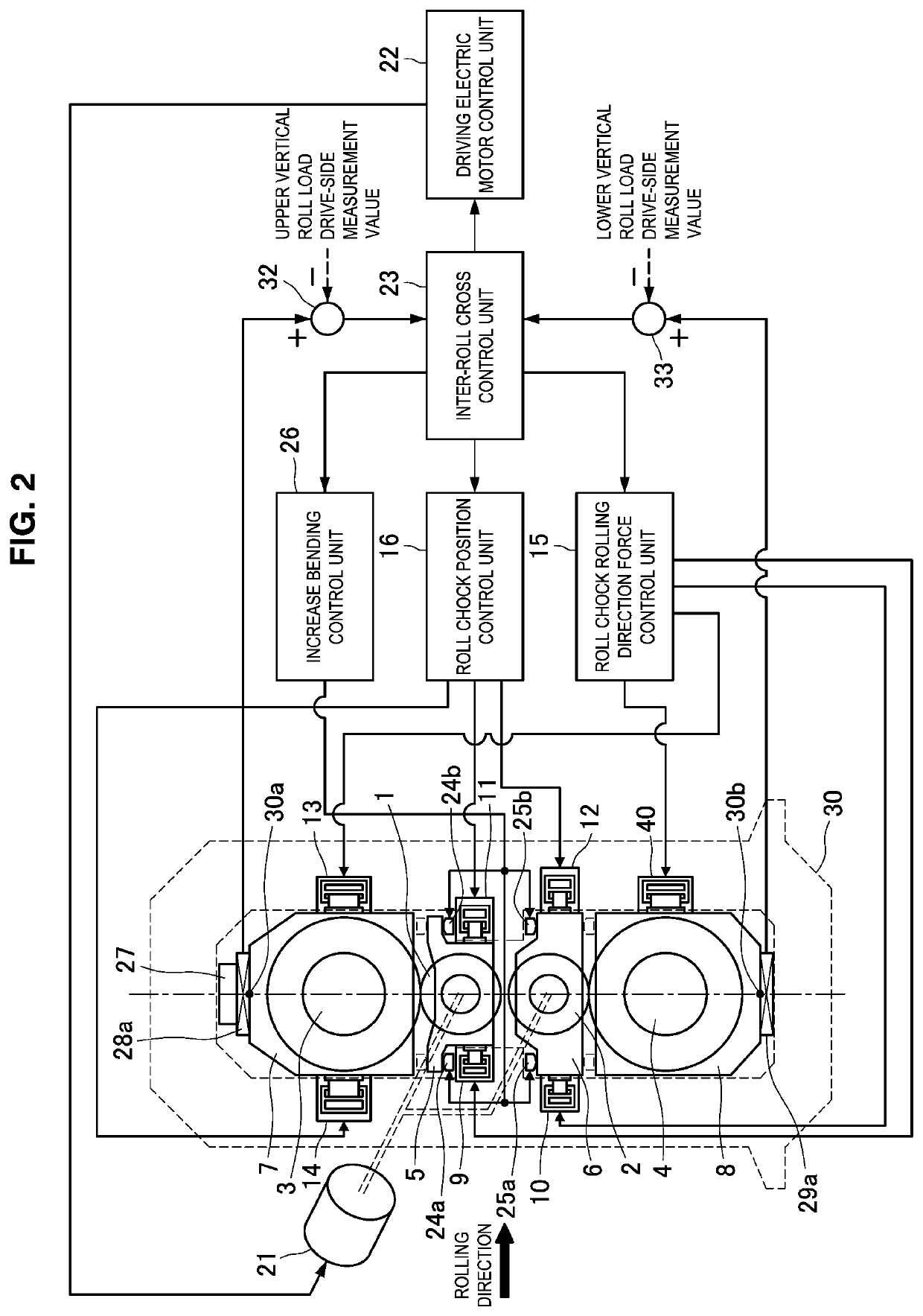
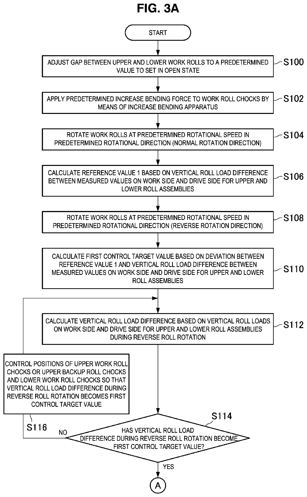
[0055]The configuration of a rolling mill according to a first embodiment of the present invention and an apparatus for controlling the rolling mill, as well as a method for setting a rolling mill will be described based on FIG. 2 to FIG. 4B. In the first embodiment, before reduction position zero point adjustment or before the start of rolling, the positions of roll chocks are adjusted so as to make an inter-roll cross angle between a backup roll serving as a reference and other rolls zero, to thereby realize rolling in which thrust forces do not arise. In the rolling mill according to the present embodiment, although thrust counterforce measurement apparatuses that measure thrust counterforces in the rolling mill are not provided, it is possible to adjust an inter-roll cross also in a case where thrust counterforces acting on the rolls cannot be measured.
[0056][2-1. Configuration of Rolling Mill]
[0057]First, the rolling mill according to the present embodiment a...
second embodiment
3. Second Embodiment
[0114]Next, a method for setting a rolling mill according to a second embodiment of the present invention will be described based on FIG. 7A to FIG. 8B. In the present embodiment, similarly to the first embodiment, before reduction position zero point adjustment or before the start of rolling, the positions of roll chocks are adjusted so as to make an inter-roll cross angle between a backup roll serving as a reference and other rolls zero, to thereby realize rolling in which thrust forces do not arise. In the rolling mill according to the present embodiment also, similarly to the first embodiment, it is possible to adjust an inter-roll cross even in a case where thrust counterforces cannot be measured. Note that, the rolling mill according to the present embodiment and the apparatus for controlling the rolling mill can be configured similarly to the rolling mill and the apparatus for controlling the rolling mill according to the first embodiment that are illustra...
example 1
[0157]A conventional method and the method of the present invention were compared with respect to fifth to seventh stands of a hot finish rolling mill having the configuration illustrated in FIG. 2, in relation to reduction leveling setting that takes into consideration the influence of inter-roll thrust forces generated due to an inter-roll cross.
[0158]First, in the conventional method, without using the functions of the inter-roll cross control unit of the present invention, replacement of housing liners and chock liners was periodically performed, and equipment management was conducted so that an inter-roll cross would not occur. As a result, in a period immediately before replacement of the housing liner, when a thin and wide material having a finished exit-side plate thickness of 1.2 mm and a width of 1500 mm was rolled, zigzagging of 100 mm or more occurred at the sixth stand, and tail crash occurred as a result.
[0159]On the other hand, in the method of the present invention, ...
PUM
| Property | Measurement | Unit |
|---|---|---|
| Force | aaaaa | aaaaa |
Abstract
Description
Claims
Application Information