Supercharge Your Innovation With Domain-Expert AI Agents!

Rotary Arc Patella Articulating Geometry

a rotary arc and articulating geometry technology, applied in the field of patellar implants, can solve the problems of not providing the required axial rotational freedom, design does not accurately replicate the natural patellar articulating geometry, and the median ridge-trochlear groove alignment is generally difficult to maintain

Pending Publication Date: 2021-03-25
HOWMEDICA OSTEONICS CORP
View PDF1 Cites 0 Cited by
  • Summary
  • Abstract
  • Description
  • Claims
  • Application Information

AI Technical Summary

Benefits of technology

The solution enables precise alignment and secure fixation of patellar implants, maintaining natural patellofemoral kinematics and maximizing bone preservation by allowing for varying thickness and dual attachment methods, reducing the risk of implant damage and bone fragmentation.

Problems solved by technology

However, this design does not accurately replicate natural patellar articulating geometry.
However, aligning the median ridge of the anatomically shaped articulating patellar implants with the native femoral trochlear groove may be challenging, and this design may not provide required axial rotational freedom.
Even if aligned properly, the median ridge-trochlear groove alignment is generally difficult to maintain.
Simple planar shapes limit patella implant design and may prevent patellar implant designs with varying thickness.
For example, increasing the thickness of the patellar implant in regions of high mechanical stress and decreasing the thickness of the patellar implant in regions where maximizing bone preservation is desired are generally not possible on account of the simple planar shapes at the bone interfacing surfaces.
Onlay technique, however, may require extensive patellar bone removal.
While the inlay technique may require less patellar bone removal, the patellar implant may not be embedded deep enough into the patella to provide the same level of fixation as achieved by utilizing an onlay technique.
Further, the inlay technique may result in sharp, jagged bone fragments along the interface with the patellar implant and may consequently damage the patellar implant.

Method used


Image

  • Rotary Arc Patella Articulating Geometry
  • Rotary Arc Patella Articulating Geometry
  • Rotary Arc Patella Articulating Geometry

Examples


Embodiment Construction

[0038]In describing preferred embodiments of the disclosure, reference will be made to directional nomenclature used in describing the human body. It is noted that this nomenclature is used only for convenience and that it is not intended to be limiting with respect to the scope of the invention.

[0039]As used herein, when referring to bones or other parts of the body, the term “anterior” means toward the front part or the face and the term “posterior” means toward the back of the body. The term “medial” means toward the midline of the body and the term “lateral” means away from the midline of the body. The term “superior” means closer to the heart and the term “inferior” means more distant from the heart.

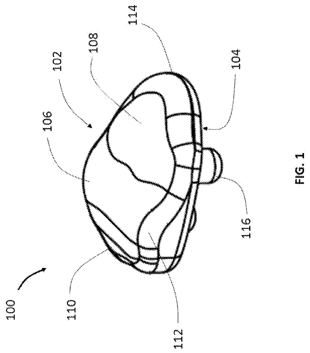
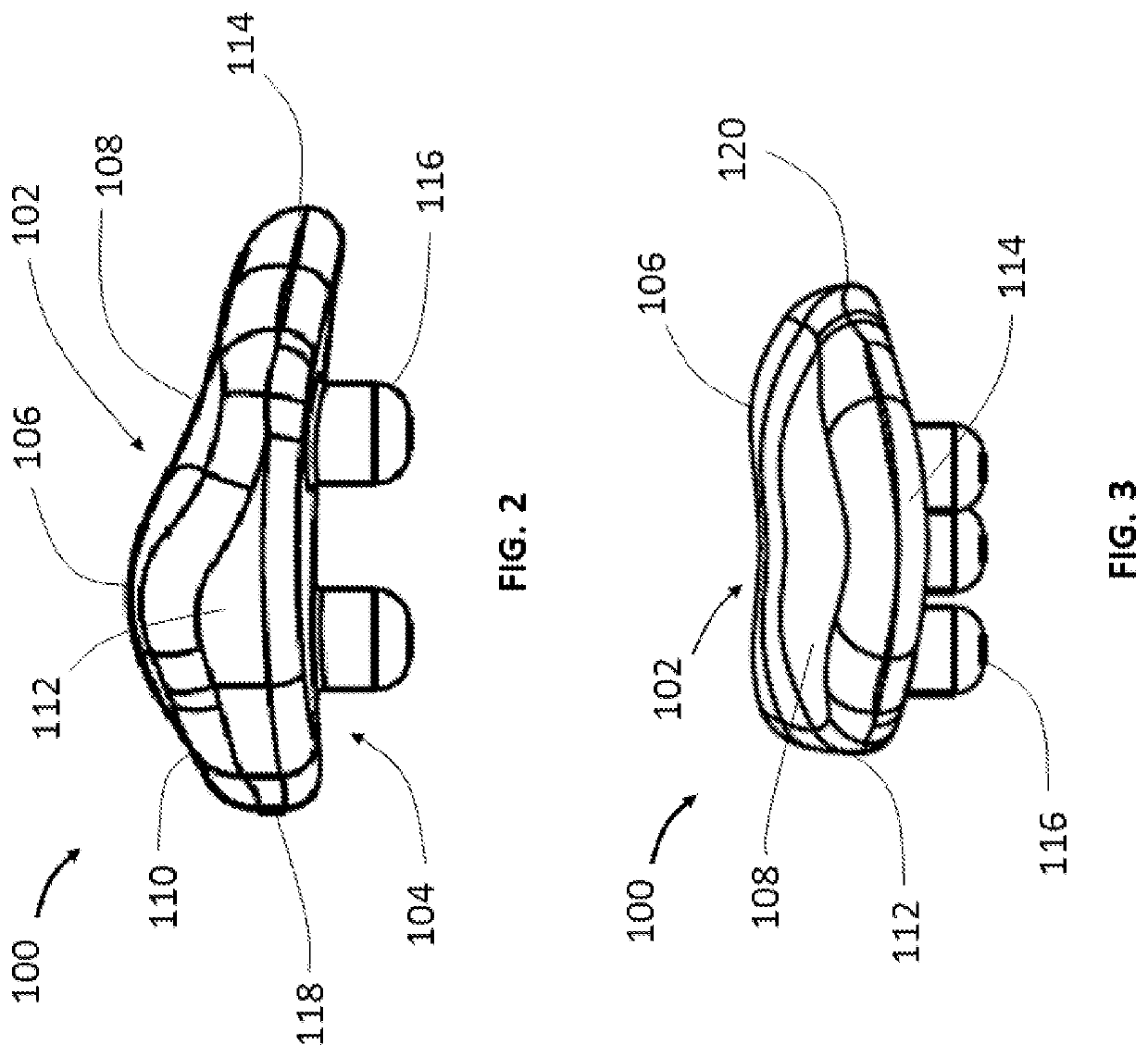
[0040]Referring now to FIGS. 1, 2 and 3, there is shown a patellar implant 100 in different views. Patellar implant 100 includes an articulating posterior surface 102 and an opposite anterior surface 104. Posterior surface 102 articulates with a distal end portion of a femoral body ...


PUM


Abstract

Disclosed herein are patellar implants and methods to prepare bone for receiving the same. The patellar implant may include an articulating surface with an elliptically shaped median ridge. The anterior surface of the patellar implant may have a non-planar surface to engage with a resected natural patella. The non-planar surface may allow for varying thickness of the patellar implant. The patellar implant may include dual attachment features to secure patellar implant to a resected patella by onlay and inlay techniques. A method for attaching a patellar implant to a patella may include onlay and inlay techniques and may further include bone preparation at the implant-bone interface.

Description

CROSS-REFERENCE TO RELATED APPLICATIONS[0001]This application is a divisional of U.S. application Ser. No. 16 / 170,311, filed on Oct. 25, 2018, which claims the benefit of the filing of U.S. Provisional Patent Application No. 62 / 580,575, filed Nov. 2, 2017, the disclosure of which is hereby incorporated herein by reference.FIELD OF INVENTION[0002]The present invention relates to medical implants for bone and methods for bone preparation, and in particular to patellar implants and methods for preparing bone to receive the same.BACKGROUND OF THE INVENTION[0003]Patella resurfacing is routinely performed for treatments of various knee ailments including arthritis. After resurfacing the patella, a surgeon may implant a patellar implant on the resurfaced patella. The patellar implant generally has a patella contacting surface for engaging the resurfaced patella and an opposite surface that articulates with a distal end of a femoral body. The articulating surface of the patellar implant may...

Claims


Application Information

Patent Timeline
Patent Type & Authority Applications(United States)
IPC IPC(8): A61F2/38
CPCA61F2/3877A61F2002/30892A61F2002/30878A61F2002/30934A61F2230/0008A61F2002/30125
Inventor AXELSON, JR., STUART L.DAVIGNON, ROBERTBHATTACHARYA, SANGHITAFERKO, MICHAEL C.WELLINGS, PETER
Owner HOWMEDICA OSTEONICS CORP
Features
  • R&D
  • Intellectual Property
  • Life Sciences
  • Materials
  • Tech Scout
  • Unparalleled Data Quality
  • Higher Quality Content
  • 60% Fewer Hallucinations
Learn More