
Suctioning Device Having Optimized Dust Suctioning

a suction device and suction chamber technology, applied in the direction of grinding machine components, manufacturing tools, separation processes, etc., can solve the problems of difficult cleaning of grinding elements, and achieve the effect of eliminating the layer

Pending Publication Date: 2021-03-25
HOMAG GMBH
View PDF4 Cites 0 Cited by
  • Summary
  • Abstract
  • Description
  • Claims
  • Application Information

AI Technical Summary

Benefits of technology

The proposed suctioning device and method help to break up the boundary layer of a grinding element while it is in use. This allows particles trapped in the boundary layer to be released, improving the efficiency of the device and reducing the time needed to achieve a grinding result. The device can also be cleaned more effectively, resulting in a better surface quality. The manipulation apparatus can easily be adjusted to different machining parameters to adapt its effect on the boundary layer.

Problems solved by technology

This layer of air (boundary layer) prevents a “break-out” of particles from the surface of the grinding element, thus making cleaning the grinding element more difficult.

Method used


Image

  • Suctioning Device Having Optimized Dust Suctioning
  • Suctioning Device Having Optimized Dust Suctioning
  • Suctioning Device Having Optimized Dust Suctioning

Examples


Embodiment Construction

[0048]Preferred embodiments of the present invention will be described in detail below using the enclosed figures. Each of the further modifications of certain features cited in this context can be combined individually with each other to create new embodiments.

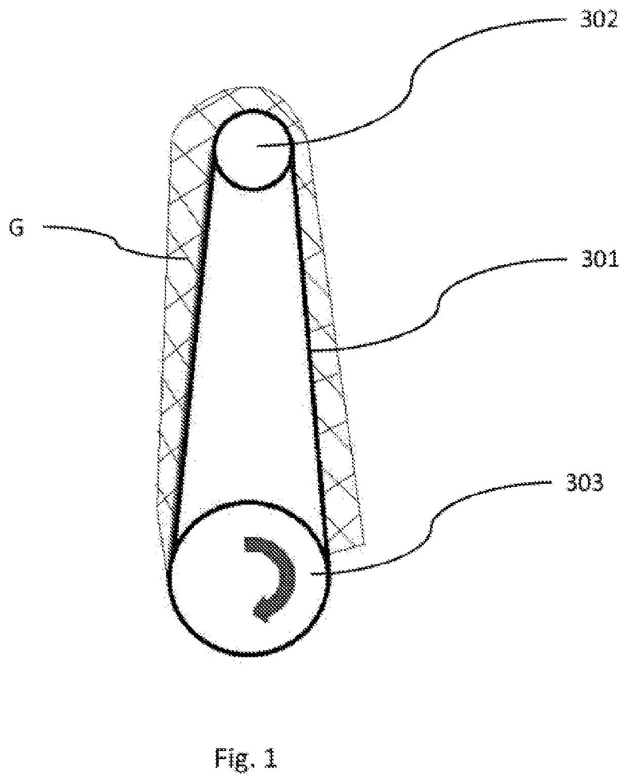
[0049]FIG. 1 shows a schematic representation of the formation of a boundary layer G on a circulating grinding belt 301 (grinding element). In the exemplary illustration shown, the grinding belt 301 is picked up vertically by a top deflection roller 302 and a bottom deflection roller 303 and is driven in a clockwise direction.

[0050]As can also be seen in FIG. 1, a boundary layer G is created as a result of the friction between a surface of the grinding belt 301 and the air contiguous to the surface of the grinding belt. In other words, the contiguous air is swept along by the grinding belt 301 due to the friction. It is also evident from FIG. 2 that the thickness of the boundary layer respectively increases from one deflectio...


PUM

PropertyMeasurementUnit
Shapeaaaaaaaaaa
Particle sizeaaaaaaaaaa
Distanceaaaaaaaaaa

Abstract

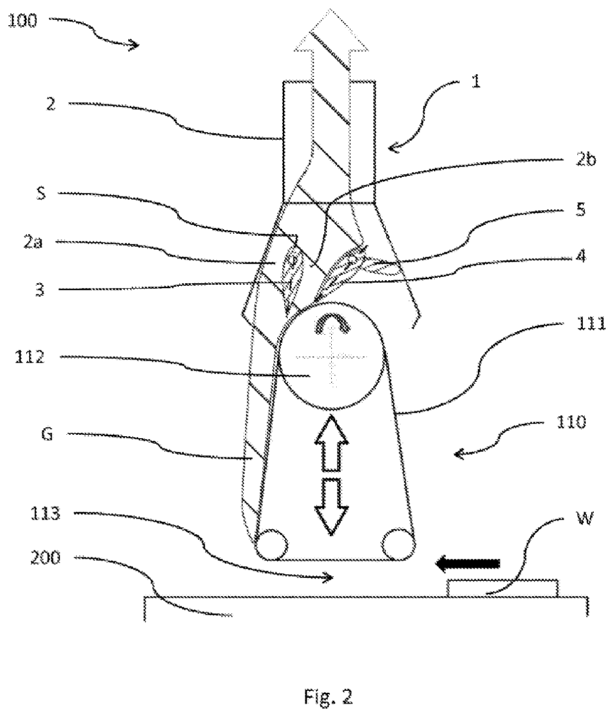
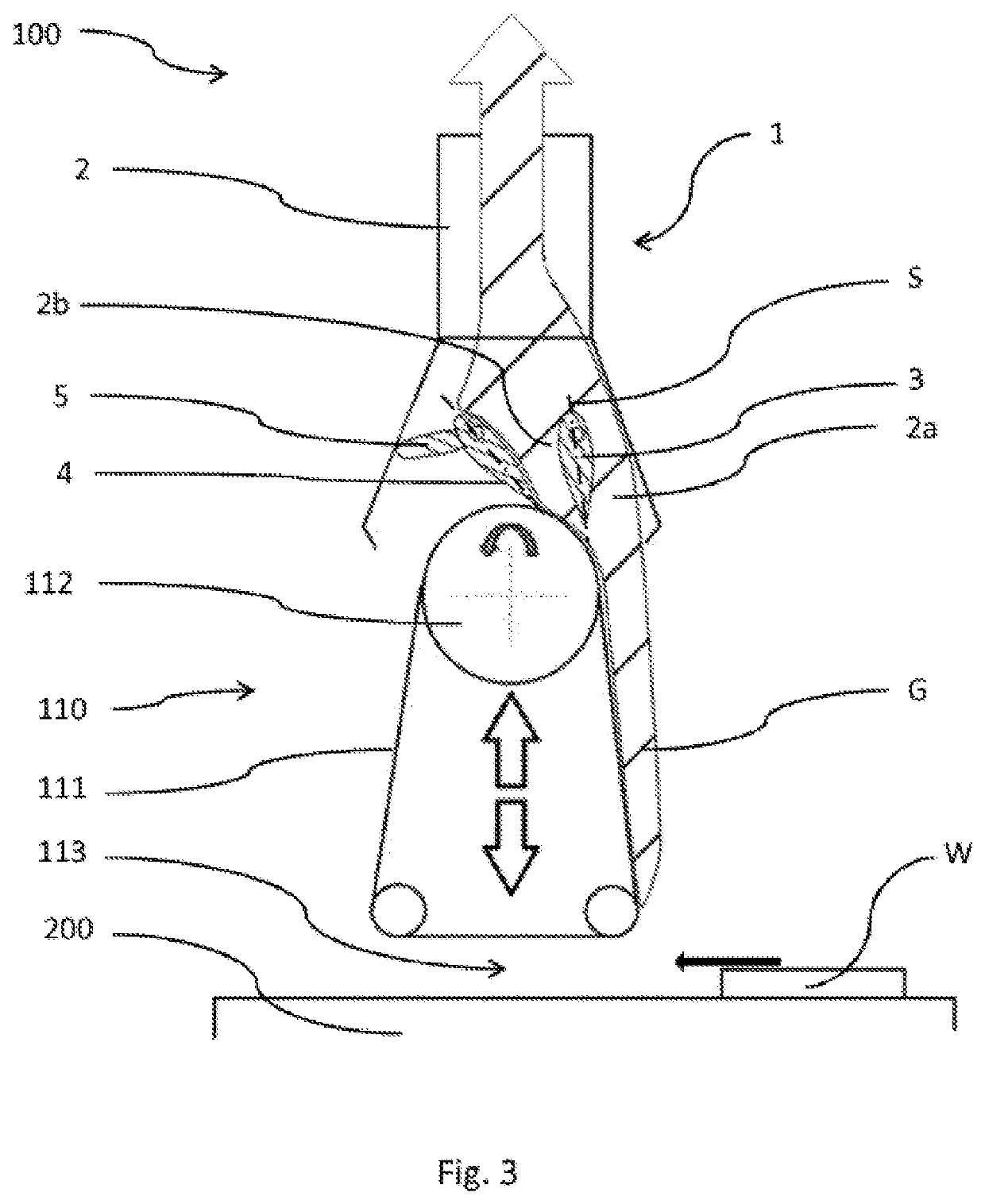
By means of the present invention, a suctioning device (1) for a grinding device (100) and a method for suctioning particles produced at a grinding device (100) are provided. The suctioning device (1) has at least one suctioning channel (2), through which suctioned air can flow, and one first manipulation apparatus (3) arranged in the suctioning channel (2). The first manipulation apparatus (3) is designed to be able to directly or indirectly influence a boundary layer (G), in particular a boundary layer (G) of a circulating grinding element (111) of a grinding device (100), in particular to be able to reach into the boundary layer (G).

Description

TECHNICAL FIELD[0001]The present invention relates to a suctioning device for a grinding device, preferably a belt grinding device, in particular for a wide belt grinding device, for optimized suctioning of particles produced during machining of a workpiece, which preferably consists at least in part of wood, composite wood materials, wood substitute materials, plastic, metal or similar. In addition, the present invention relates to a method for suctioning particles produced during machining on a grinding device, and to a grinding device having a suctioning device according to the invention.[0002]The (dust) suctioning device and method of the present invention are particularly used in wide belt grinding machines, preferably for machining plate-shaped workpieces.PRIOR ART[0003]Devices and methods for suctioning particles produced during machining, in particular chipping, are already known from the prior art. A device for removing grinding dust from workpieces in a grinding device whi...

Claims


Application Information

Patent Timeline
IPC IPC(8): B24B55/08B23Q11/00B24B49/10
CPCB24B55/08B24B49/10B23Q11/006B01D45/16B24B21/04B23Q11/0046
Inventor HELLMANN, TORBEN
Owner HOMAG GMBH
Learn More