Method of manufacturing electronic device

Active Publication Date: 2021-03-25
DAEGU GYEONGBUK INST OF SCI & TECH
View PDF0 Cites 0 Cited by
  • Summary
  • Abstract
  • Description
  • Claims
  • Application Information

AI Technical Summary

Benefits of technology

The patent text describes a method of manufacturing electronic devices by peeling off a layer from a substrate and transferring it to another substrate. This process can cause damage and deformation of the electronic device, and the technical problem that this patent aims to solve is how to reduce these damages and deformations while still achieving complex shapes of electronic devices.

Problems solved by technology

However, when the electronic device is peeled off from the transfer substrate, the arrangement of the electronic device may be different from an initial arrangement due to the flow of a solution used for the detachment, or the electronic device may be damaged by a laser.

Method used

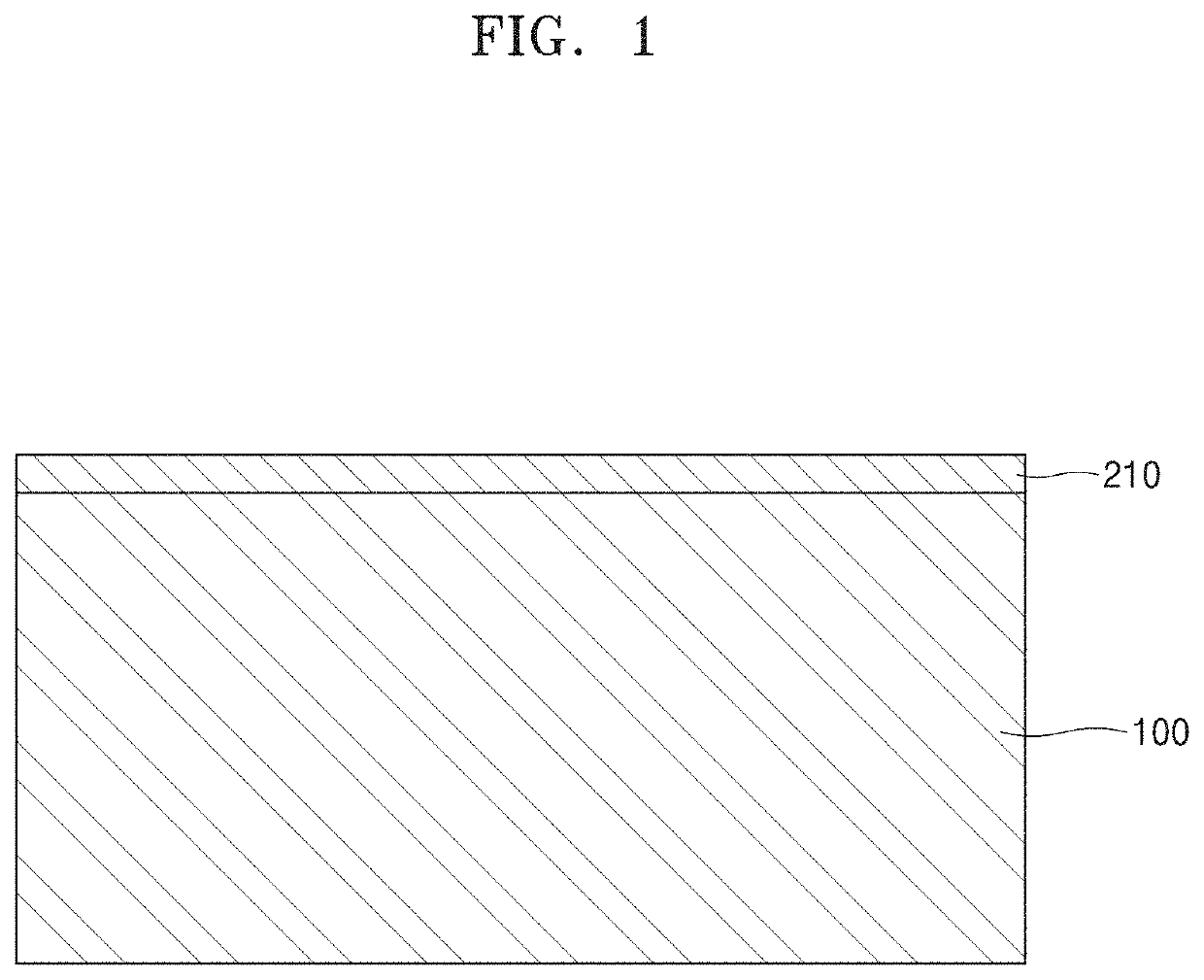
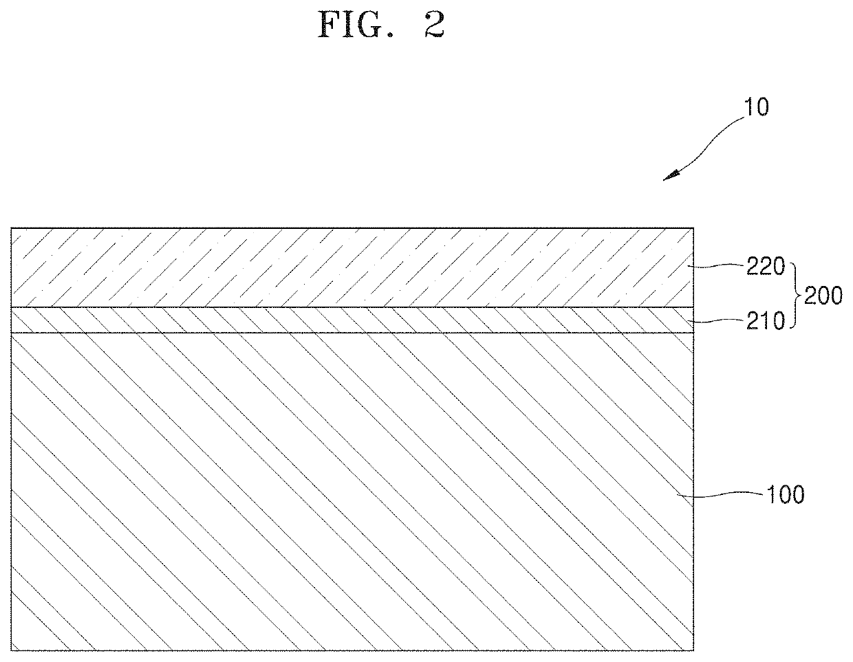
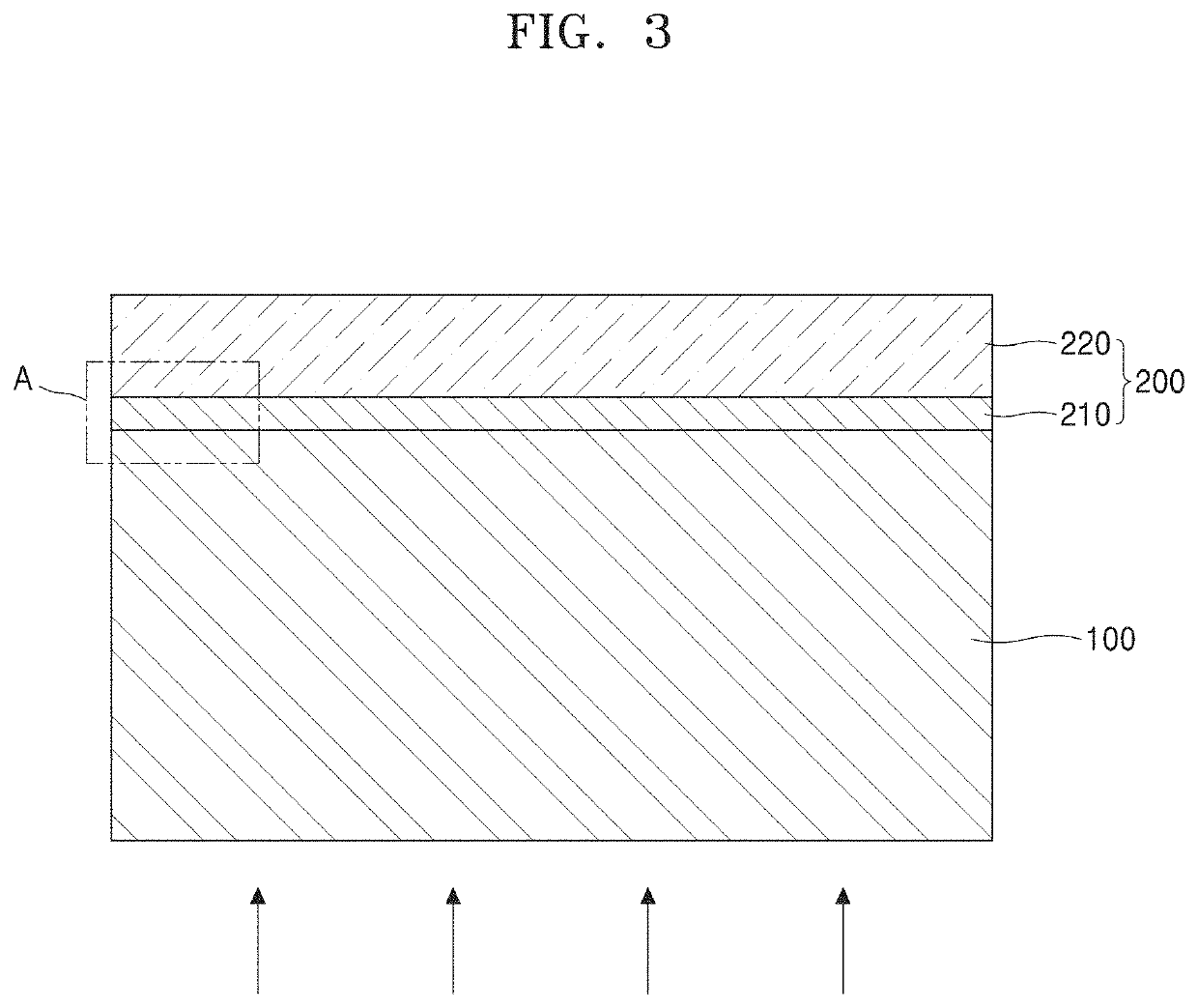

Image

  • Method of manufacturing electronic device
  • Method of manufacturing electronic device
  • Method of manufacturing electronic device

Examples


Embodiment Construction

[0034]Reference will now be made in detail to embodiments, examples of which are illustrated in the accompanying drawings, wherein like reference numerals refer to like elements throughout. In this regard, the present embodiments may have different forms and should not be construed as being limited to the descriptions set forth herein. Accordingly, the embodiments are merely described below, by referring to the figures, to explain aspects of the present description. As used herein, the term “and / or” includes any and all combinations of one or more of the associated listed items. Expressions such as “at least one of,” when preceding a list of elements, modify the entire list of elements and do not modify the individual elements of the list.

[0035]It will be understood that although the terms “first”, “second”, etc. may be used herein to describe various components, these components should not be limited by these terms. The terms are only used to distinguish one component from another....


PUM


Abstract

A method of manufacturing an electronic device is provided. The method includes forming a stack structure by placing a to-be-peeled layer on a substrate, applying thermal shock to the stack structure, detaching the to-be-peeled layer from the substrate, and transferring the detached to-be-peeled layer to a target substrate.

Description

CROSS-REFERENCE TO RELATED APPLICATION[0001]This application claims priority to Korean Patent Application No. 10-2019-0116259, filed on Sep. 20, 2019 in the Korean Intellectual Property Office, the entirety of which is hereby incorporated by reference herein.BACKGROUND1. Field[0002]One or more embodiments relate to a method of manufacturing an electronic device, and more particularly, to a method of manufacturing an electronic device, the method being capable of reducing damage and deformation of an electronic device which occur in the process of peeling off the electronic device, and manufacturing a large-area electronic device having a complex shape.2. Description of Related Art[0003]In general, when manufacturing an electronic device, an electronic device may be directly formed on a transfer target to be a component of the electronic device. However, if necessary, the electronic device may be formed on a transfer substrate and then peeled off from the transfer substrate and trans...

Claims


Application Information

Patent Timeline
IPC IPC(8): H01L21/683B32B37/00C09J5/00C09J7/38
CPCH01L21/6835B32B37/025C09J5/00C09J7/38C09J2205/302H01L2221/68363B32B2457/00C09J2203/326H01L2221/68386B32B7/06Y02P70/50H10K71/18H10K71/80H01L21/7806H01L21/02266H01L21/324H01L21/768H01L24/50C09J2301/502B32B38/10B32B43/006
Inventor JANG, KYUNG INKEUM, HO HYUNRAH, JONG CHEOLHEO, SEUNG KYOUNG
Owner DAEGU GYEONGBUK INST OF SCI & TECH
Why Eureka
Try Eureka