
Mounting assembly, panel light having mounting assembly and panel light combination

a technology of mounting assembly and mounting light, which is applied in the direction of lighting and heating apparatus, semiconductor devices for light sources, lighting support devices, etc., can solve the problems of difficult or even impossible adjustment of the angle between neighboring panel lights, and the difficulty of detachment of panel lights, so as to facilitate adjustment of the mounting angle

Pending Publication Date: 2021-04-01
NANOGRID
View PDF0 Cites 1 Cited by
  • Summary
  • Abstract
  • Description
  • Claims
  • Application Information

AI Technical Summary

Benefits of technology

The present invention provides a mounting assembly for panel lights that overcomes the difficulties of previous design. The invention allows for easier detachment and adjustment of the panel lights without damaging them. This results in a more flexible and convenient installation process.

Problems solved by technology

Panel lights are however difficult to detach, and the conventional mounting manner makes it inconvenient, difficult or even impossible to adjust an angle between neighboring panel lights during the mounting.

Method used


Image

  • Mounting assembly, panel light having mounting assembly and panel light combination
  • Mounting assembly, panel light having mounting assembly and panel light combination
  • Mounting assembly, panel light having mounting assembly and panel light combination

Examples


Embodiment Construction

[0034]In order to more clearly illustrate the technical solutions in embodiments of the present invention, figures are used. Obviously, the figures described below are only some embodiments illustrating the present invention. Those ordinary skilled in the art will appreciate that other figures may be obtained according to these figures without making any inventive efforts.

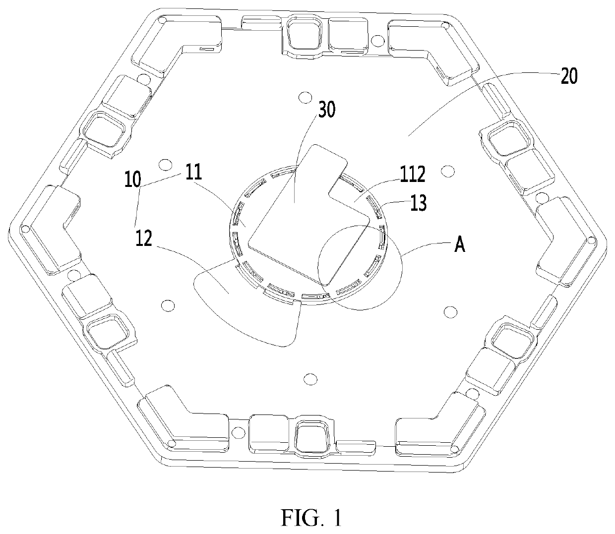
[0035]FIG. 1 is an embodiment illustrating a mounting assembly of the present invention, wherein a mounting member is connected to a base plate;

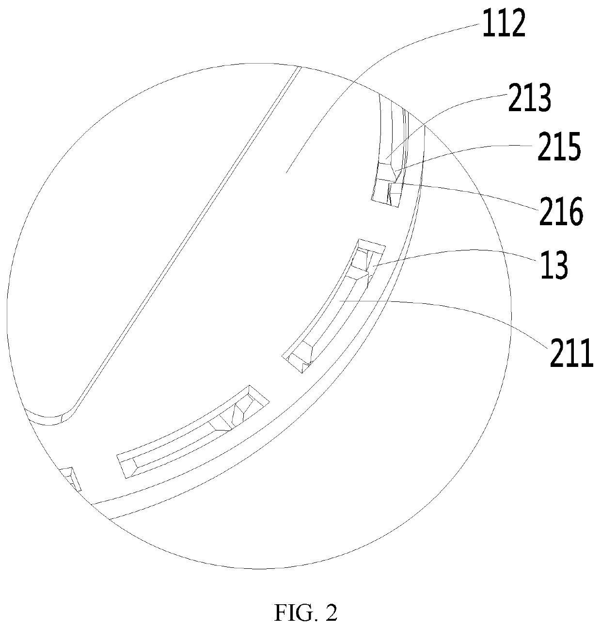
[0036]FIG. 2 is a partial enlarged view of a portion A of FIG. 1;

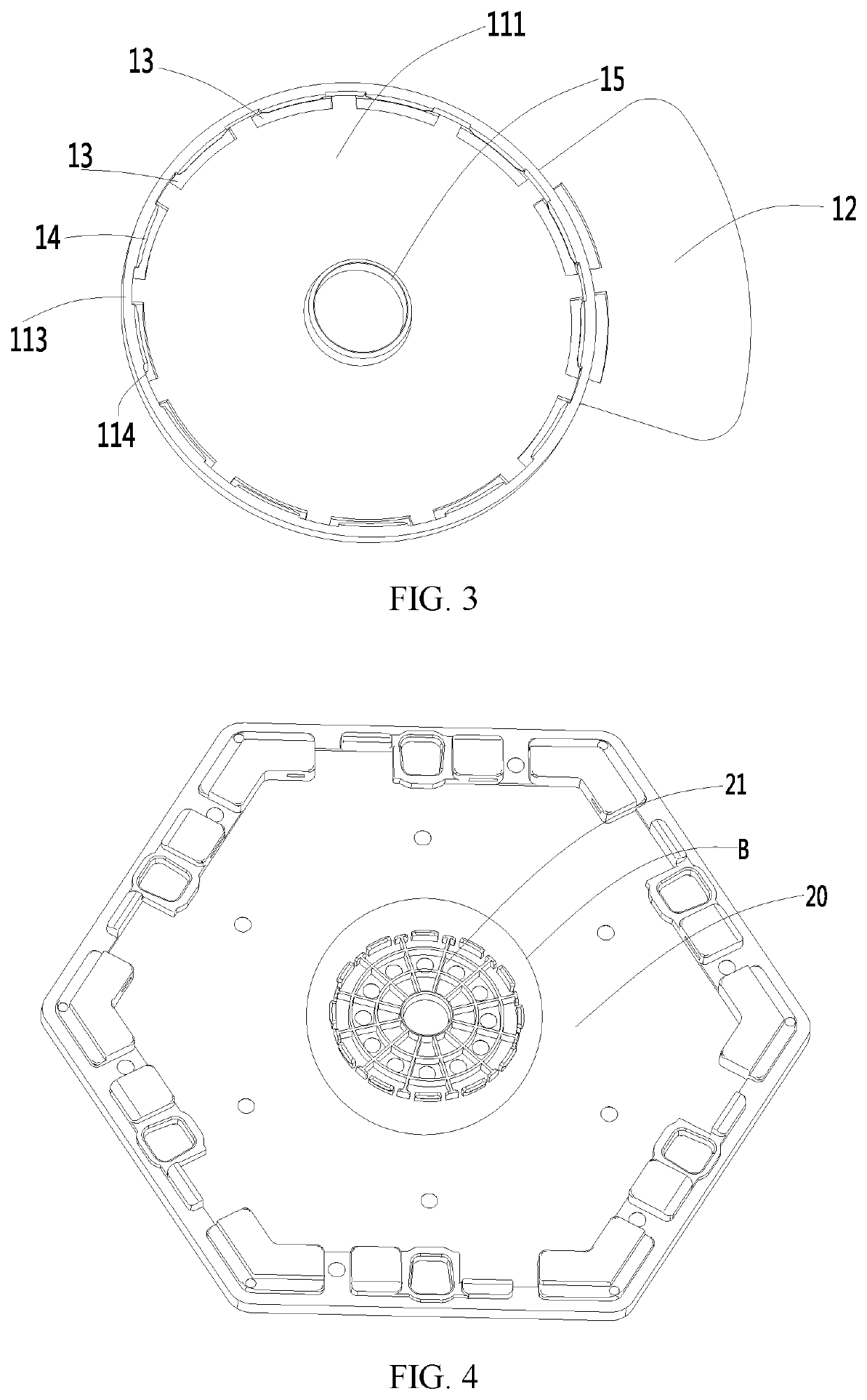
[0037]FIG. 3 is a structural view of a mounting member in a mounting assembly according to an embodiment of the present invention;

[0038]FIG. 4 is a structural view of a base plate in a mounting assembly according to an embodiment of the present invention;

[0039]FIG. 5 is a partial enlarged view of a portion B of FIG. 4.

[0040]In the figures, the same reference numerals indicate the same features, specifically as...


PUM


Abstract

The present invention relates to a mounting assembly, a panel light having the mounting assembly and a panel light combination. The mounting assembly has a mounting member including a first surface connectable to a mounting position, a second surface opposite the first surface, and a generally circular ring-shaped first connecting portion formed by extending outwardly along the second surface. There is also provided with a base plate connected to the mounting member, with a middle portion of the base plate extending outwardly to form a second connecting portion detachably connected to the first connecting portion. The first connecting portion is further configured to be movably engaged with the second connecting portion such that the base plate can adjust a mounting angle relative to the mounting member.

Description

CROSS REFERENCE TO RELATED APPLICATION[0001]This application claims priority from earlier filed Chinese Patent Application No. 201921623881.7 filed Sep. 26, 2019, contents of which are incorporated herein in its entirety.FIELD OF THE INVENTION[0002]The present invention relates to the technical field of structures of lighting apparatus, and particularly to a mounting assembly, a panel light having the mounting assembly and a panel light combination having the panel lights.BACKGROUND OF THE INVENTION[0003]LED panel lights achieve a uniform planar illumination effect after the light passes through a light guide plate with high transmittance, and exhibit good illumination uniformity, soft light, comfort and brightness; therefore, the LED panel lights have gradually become a mainstream indoor lighting fixture.[0004]LED panel lights may also meet specific light-emitting demands and form specific light-emitting effects by splicing and combining. A conventional indoor light mounting manner...

Claims


Application Information

Patent Timeline
Patent Type & Authority Applications(United States)
IPC IPC(8): F21V21/04F21V15/01F21V19/00F21V21/096
CPCF21V21/04F21V15/01F21Y2115/10F21V21/096F21V19/0055F21V21/02F21V21/0808F21Y2105/00
Inventor RODINGER, TOMASKANG, GUOPING
Owner NANOGRID
Learn More