
Voltage-regulating circuit and regulated power-supply module

a voltage-regulating circuit and power-supply module technology, applied in the direction of electric variable regulation, process and machine control, instruments, etc., can solve the problems of disproportionate power supply cost, circuits described in the prior art, and circuits that do not allow power supply to deliver output voltage very quickly

Active Publication Date: 2021-04-01
SCHNEIDER ELECTRIC IND SAS
View PDF0 Cites 2 Cited by
  • Summary
  • Abstract
  • Description
  • Claims
  • Application Information

AI Technical Summary

Benefits of technology

[0010]a control circuit connected to the first comparing circuit, to the second comparing circui

Problems solved by technology

Power supplies using voltage transformers are widely used for their low cost; however, they require a sinusoidal input voltage and transformers are components that can be bulky or difficult to fit into a power-supply module.
In contrast, when the equipment consumes very little power (typically a few hundred watts maximum) and is connected to a distributing network delivering a high input voltage (240 volts for examp

Method used


Image

  • Voltage-regulating circuit and regulated power-supply module
  • Voltage-regulating circuit and regulated power-supply module
  • Voltage-regulating circuit and regulated power-supply module

Examples


Embodiment Construction

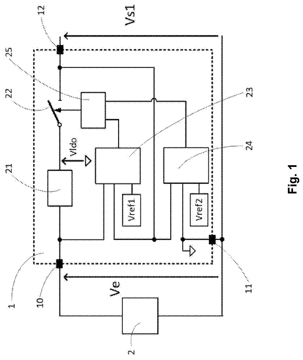
[0039]FIG. 1 shows, in the form of a block diagram, a voltage-regulating circuit 1 comprising at least an input terminal 10, a reference terminal 11 and an output terminal 12. A voltage source 2 is connected between the input terminal 10 and the reference terminal 11 and delivers an input voltage Ve. Said regulating circuit 1 is arranged to deliver a regulated output voltage Vs1 across the output terminal 12 and the reference terminal 11. To this end, the regulating circuit 1 comprises:[0040]a voltage regulator 21,[0041]a switch 22, connected in series with the voltage regulator 21 between the input terminal 10 and the output terminal 12, said switch 22 and said voltage regulator 21 forming a first assembly,[0042]a first comparing circuit 23 connected to the input terminal 10 and to the output terminal 12, said first comparing circuit 23 being arranged to compare the amplitude of the deviation between the input voltage Ve and the output voltage Vs1 to a first threshold Vref1,[0043]a...


PUM


Abstract

A voltage-regulating circuit comprising:
    • a voltage regulator,
    • a switch,
    • a first comparing circuit for comparing the amplitude deviation between the input voltage and the output voltage to a first threshold,
    • a second comparing circuit for comparing the amplitude of the output voltage to a second threshold, and
    • a control circuit for commanding the switch to open or close depending on the comparisons made by the first comparing circuit and by the second comparing circuit.
Also disclosed is a regulated power-supply module comprising such a voltage-regulating circuit.

Description

TECHNICAL FIELD[0001]The present invention relates to a voltage-regulating circuit and to a regulated power-supply module comprising such a regulating circuit.PRIOR ART[0002]Many pieces of equipment that are supplied with power by a power source, such as a network for distributing electrical power, comprise a regulated power-supply module allowing an AC or DC input voltage delivered by the distributing network to be converted into a very low DC output voltage that may be used to power electronic or electromechanical circuits. The power to be transmitted between the input and output and the deviation between the input voltage and the output voltage are factors that are preponderant in the choices made with respect to the design of such power-supply modules. Power supplies using voltage transformers are widely used for their low cost; however, they require a sinusoidal input voltage and transformers are components that can be bulky or difficult to fit into a power-supply module. It is...

Claims


Application Information

Patent Timeline
IPC IPC(8): H02M3/158H02M7/219H03K5/24
CPCH02M3/158H02M2001/0025H03K5/24H02M7/219G05F1/66H02M1/36H02M7/06G05F1/56H02M7/2176G05F3/18G05F1/468H02M1/0006H02M1/0025H02M3/156
Inventor BRENGUIER, JÉRÔME
Owner SCHNEIDER ELECTRIC IND SAS
Features
  • Generate Ideas
  • Intellectual Property
  • Life Sciences
  • Materials
  • Tech Scout
  • Unparalleled Data Quality
  • Higher Quality Content
  • 60% Fewer Hallucinations
Learn More