Humidifier for a system for providing a flow of breathable gas

Pending Publication Date: 2021-04-22
KONINKLJIJKE PHILIPS NV
View PDF5 Cites 0 Cited by
  • Summary
  • Abstract
  • Description
  • Claims
  • Application Information

AI Technical Summary

Benefits of technology

The invention is a humidifier that uses a heat pipe to efficiently capture heat from the environment without needing an external power source. This makes it easy to move and design the humidifier in a way that works best for the specific conditions. The humidifier can also have a hot end placed at the exhaust air outlet to make the most use of the hot air. This allows the humidifier to operate in a variety of environments, and ensures that the humidifier never gets too hot or too cold.

Problems solved by technology

The human airway is composed of walls of soft tissue which can collapse and thereby obstruct breathing during sleep.
The drawback of such a heating unit is usually its size and the necessity of connecting the heating unit to a power supply, which makes the system less handy and mobile.
Thus, fresh air leaving the humidifier is typically a few degrees colder than ambient temperature and the evaporation process is limited by the heat that the system can extract from the environment (typically 4-6 W for commercial CPO's).
However, such a system still demands for further improvements in terms of size, weight and humidification rate.
In order to fulfill these requirements, especially heating of humidifiers to increase humidification rate is a challenging aspect as such heated systems demand for both, a heating unit and a power supply (i.e. a battery) and thus contradict ostensibly with reduction of size and weight.

Method used


Image

  • Humidifier for a system for providing a flow of breathable gas
  • Humidifier for a system for providing a flow of breathable gas
  • Humidifier for a system for providing a flow of breathable gas

Examples


first embodiment

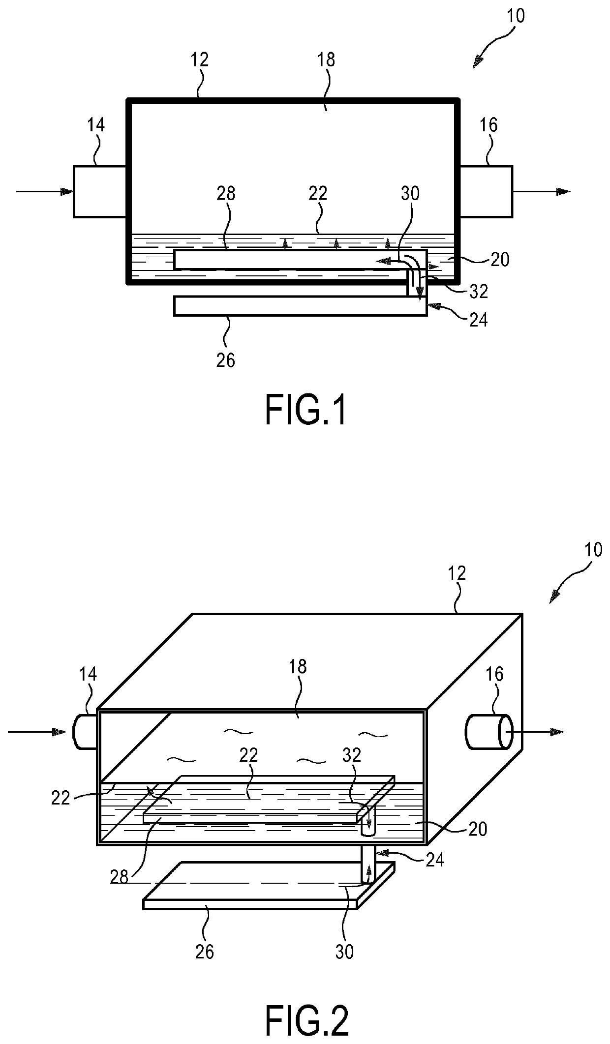
[0059]FIG. 1 shows the humidifier for a system for providing a flow of breathable gas to an airway of a patient. The humidifier is therein in its entirety denoted by reference numeral 10.

[0060]The humidifier 10 comprises a casing 12 with an air inlet 14 arranged at the left sidewall of the casing 12 and an air outlet 16 arranged at the right sidewall of the casing 12 (regarding a plane view perspective). The air inlet 14 and the air outlet 16 are connected via a flow passage 18, which is located inside the casing 12 and which is in fluidic communication with a liquid reservoir 20.

[0061]In FIG. 1, this fluidic communication mainly takes place at a boundary surface 22 between the flow passage 18 and the liquid reservoir 20 and thus, directly on or slightly above the surface 22 of the liquid reservoir 20.

[0062]The liquid reservoir 20 may e.g. contain water as a liquid. A flow of breathable gas, in this case air, may enter the humidifier 10 through the air inlet 14, accumulate evaporati...

third embodiment

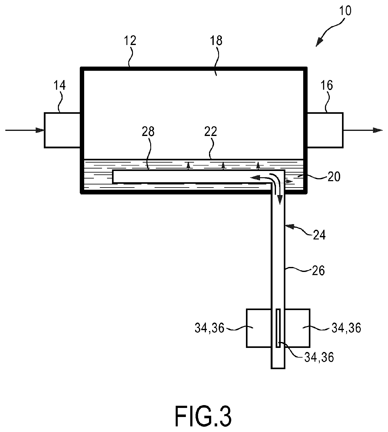
[0068]FIG. 3 shows the humidifier 10 according to the present invention. In this embodiment, the hot end 26 of the heat pipe 24 protrudes in a rectangular angle from the casing 12 of the humidifier 10, wherein the heat pipe 24 shows a substantially tubular shape. Additionally, at the end of the hot end 26 of the heat pipe 24 a heat exchanger 34 is arranged in form of fins 36, which are in thermal contact with the surface of the hot end 26 of the heat pipe 24. It is clear that the angle between the hot end 26 of the heat pipe 24 and the casing 12 does not necessarily have to be a right angle. It is however preferred that the hot end 26 protrudes from the casing 12 such that at least parts of the hot end 26 are arranged distanced from the casing 12 and are exposed to the ambient environment. The hot end 26 of the heat pipe 24 is positioned below the cold end 28 of the heat pipe 24.

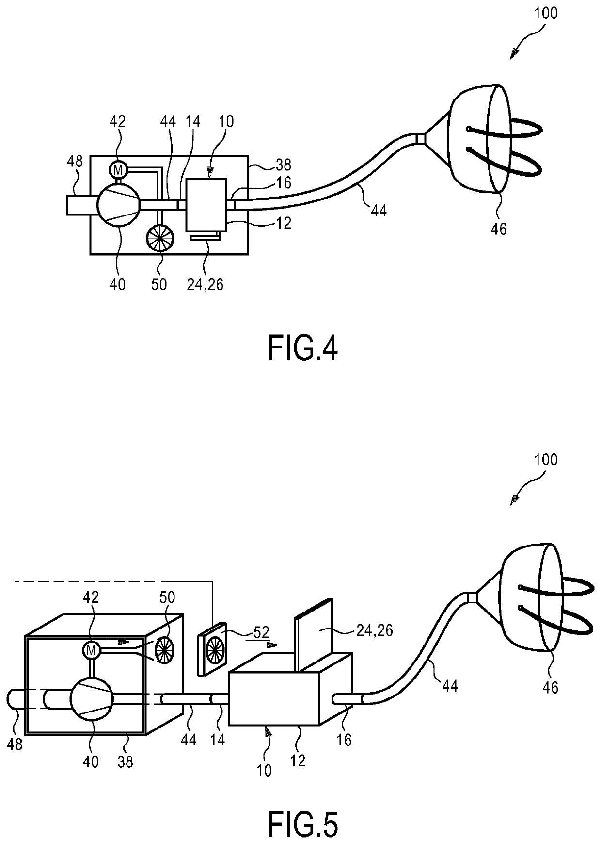
[0069]FIG. 4 shows a first embodiment of a system 100 for providing a flow of breathable gas to an airway...


PUM


Abstract

The present invention relates to a humidifier (10) for a system for providing a flow of breathable gas to an airway of a patient, wherein the humidifier (10) comprises: a casing (12) configured to contain a liquid reservoir (20); an air inlet (14) which is arranged at the casing (12); an air outlet (16) which is arranged at the casing (12); and a flow passage (18) connecting the air inlet (14) with the air outlet (16), wherein the flow passage (18) is in fluidic communication with the liquid reservoir (20), and wherein the humidifier (10) comprises a heat pipe (24) having a hot end (26) and a cold end (28), wherein the hot end (26) of the heat pipe (24) is arranged outside the casing (12) and the cold end (28) of the heat pipe (24) is arranged in the liquid reservoir (20).

Description

FIELD OF THE INVENTION[0001]The present invention relates to a humidifier for a system for providing a flow of breathable gas to an airway of a patient. The present invention further relates to the system comprising such a humidifier.BACKGROUND OF THE INVENTION[0002]Systems for providing a flow of breathable gas to an airway of a patient are applicable for the treatment and the therapy of several diseases and chronic dysfunctions where a patient needs, e.g. depending on the time of the day, supportive ventilation air or demands for a permanent ventilation. In such systems, gases like air, cleaned air, pure oxygen, or any modification thereof are delivered to the patient via a patient interface in a pressurized or unpressurized way.[0003]Depending on the type of respiratory disease, the patient either needs to be actively ventilated by a so-called ventilator or ventilation system that takes over the breathing function of the patient, or the patient's breathing function needs to be me...

Claims


Application Information

Patent Timeline
IPC IPC(8): A61M16/10
CPCA61M16/1095A61M2205/366A61M2205/3606A61M2205/362A61M16/0063A61M16/0066A61M16/0683A61M16/0875A61M16/16A61M2205/3666A61M2205/8212A61M16/109
Inventor LOUWSMA, HENDRIK KLAASSTOLK, THEODOOR
Owner KONINKLJIJKE PHILIPS NV
Why Eureka
Try Eureka