Optical fiber with mode sink

a technology of optical fiber and mode sink, which is applied in the field of optical fiber, can solve the problems of not carrying out detailed vertical bending analysis at that time, affecting the quality of optical fiber, and difficult to meet contradicting requirements with conventional fibers, etc., and achieves less sensitive, large dimensions, and larger refractive index differences.

Active Publication Date: 2009-04-14
VALTION TEKNILLINEN TUTKIMUSKESKUS
View PDF4 Cites 1 Cited by
  • Summary
  • Abstract
  • Description
  • Claims
  • Application Information

AI Technical Summary

Benefits of technology

[0022]The advantage of the invention is that the propagation loss of the fundamental mode is significantly less sensitive to the radius of the fiber bending curvature than in traditional fibers with similar dimensions and same number of propagating modes. Also with respect to traditional fibers the number of propagating modes is significantly less sensitive to the radius of the fiber bending curvature. Compared to conventional fibers the fiber according to the invention can be single-moded with large dimensions and larger refractive index difference. The optical fiber according to the invention is therefore very suitable to be used in high-power fibre lasers where large mode area and freedom in glass doping are particularly valuable. Because the fiber is significantly more flexible in the direction perpendicular to the plane of the slab than in the plane of the slab, the disadvantageous bending in the plane of the slab is practically hindered.
[0023]In one embodiment of the optical fiber the overall structure of the fiber's cross-section is significantly wider than it is thick.
[0024]In one embodiment of the optical fiber the higher order modes are cut off due to the presence of the slab and the effective index difference is significantly smaller than the refractive index difference between the core and the cladding. Thus, modal behaviour of the fiber is at least similar to that of a rib waveguide on a planar substrate or a previously known rib fiber. The difference with respect to the said known rib waveguides and rib fibers is that the fiber bends only in the vertical direction, i.e. perpendicularly to the plane of the slab.
[0025]In one embodiment of the optical fiber one lateral edge of the slab is in the vicinity of the core while the other lateral edge extends far away from the core, so that the slab extends only to one direction away from the core.
[0026]In one embodiment of the optical fiber the core is in the vicinity of the center region of the slab and both lateral edges of the slab extend to substantially opposite directions away from the core.
[0027]In one embodiment of the optical fiber one, two, three or four separate slabs are placed into the vicinity of the core, each having at least one lateral edge extending far away from the core.

Problems solved by technology

However, no detailed analysis of vertical bending was carried out at that time.
The rib fibers were then forgotten, probably because they had higher scattering and bending losses and they were more fragile than the alternative fiber structures.
These contradicting requirements are difficult to fulfill with conventional fibers.
However, it is not very convenient to have a fixed radius of curvature.
Based on the experimental work carried out with slab-coupled waveguides on planar substrates, the main disadvantage is their sensitivity to bending, which leads to the use of very long bending radii and poor miniaturization.
In planar technology there is no way to take advantage of the smaller sensitivity to bending in the vertical direction.

Method used


Image

  • Optical fiber with mode sink
  • Optical fiber with mode sink
  • Optical fiber with mode sink

Examples


Embodiment Construction

[0040]Reference will now be made in detail to the embodiments of the present invention, examples of which are illustrated in the accompanying drawings.

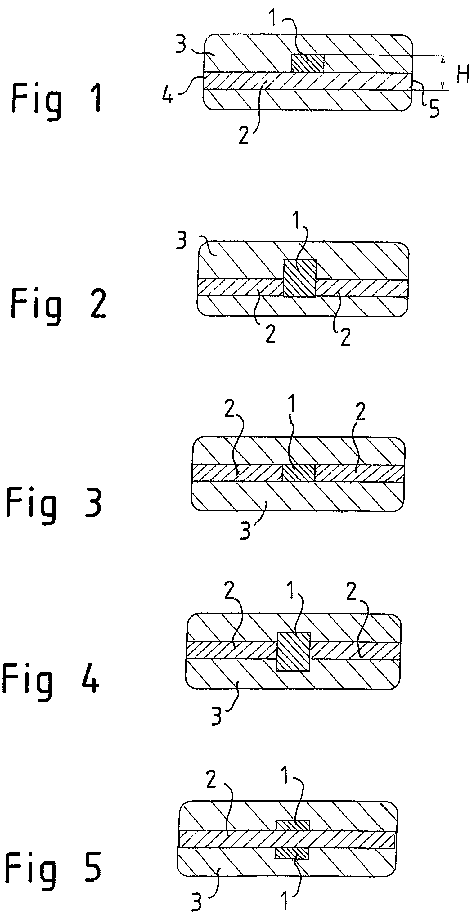
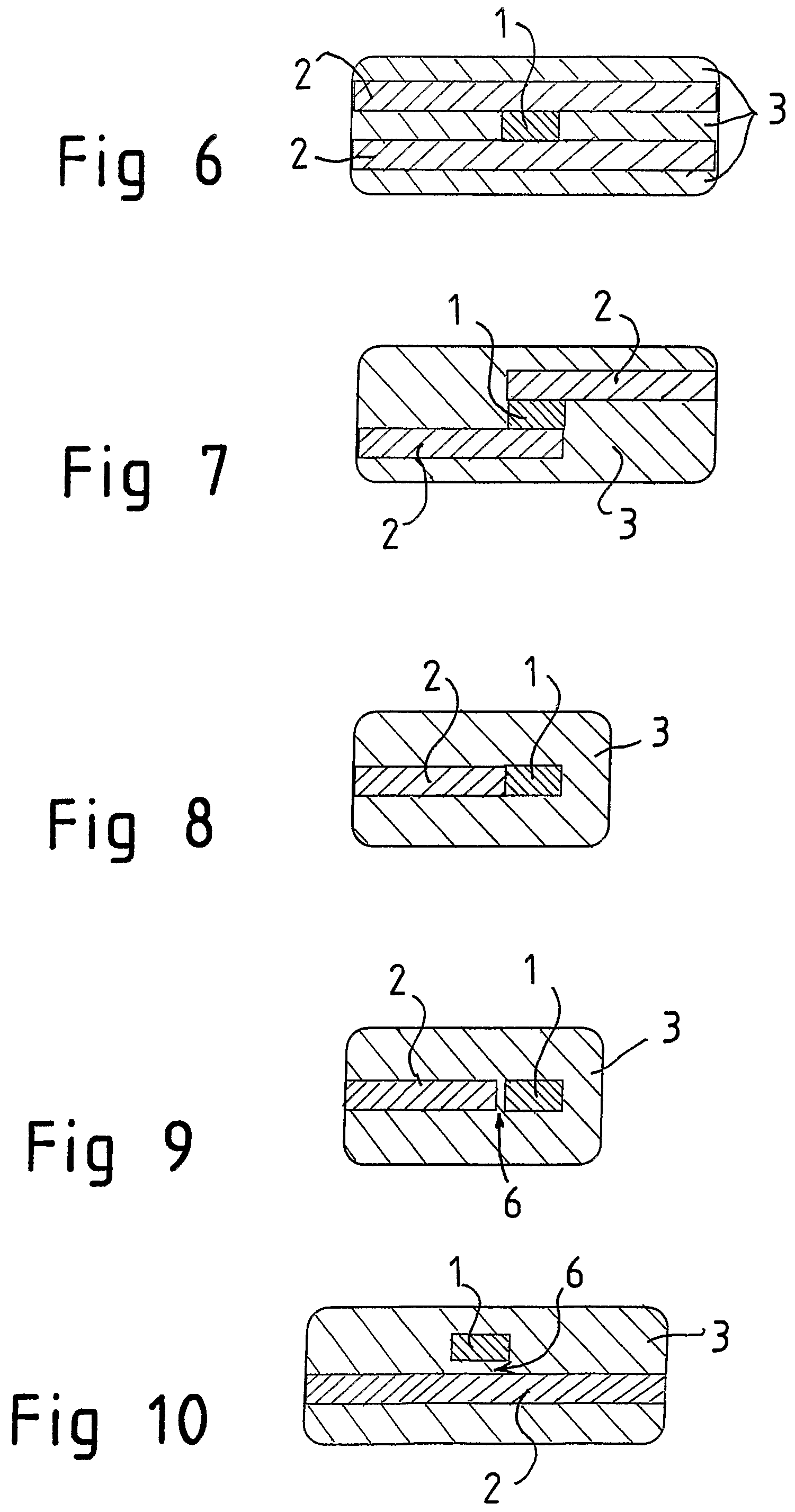
[0041]FIGS. 1-12 show optical fibers which act as slab-coupled waveguides and in which the mutual arrangement of core and slab vary.

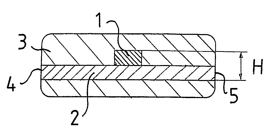
[0042]In all embodiments the optical fiber has a core 1, which is responsible for the horizontal confinement of the fiber's fundamental mode. In all FIGS. 1-12 the core is illustrated as a simple rectangle, but it should be noted that the core may have an arbitrary two-dimensional shape, and it may be e.g. circular. It may also be made of several materials.

[0043]Further, the fiber comprises a slab 2 which is placed in the vicinity of the core. The slab 2 extends substantially in a plane. The slab acts as a mode sink for the core 1 and is at least three times wider than the core 1. In all FIGS. 1-12 the slab is illustrated as a simple rectangle, although it can have a more complicated structure. In particu...


PUM


Abstract

The present invention concerns an optical fiber acting as a slab-coupled waveguide. The optical fiber has a cross-section comprising a core (1), which is two dimensional and responsible for the horizontal confinement of the fiber's fundamental mode. A slab (2) is placed in the vicinity of the core (1). The slab (2) extends substantially in a plane, acts as a mode sink for the core, and is at least three times wider than the core (1). A cladding (3) surrounds the core (1) and the slab (2). The cladding (3) is made of one or several materials with refractive indices lower than the core and slab materials. The core (1), slab (2) and cladding (3) and any other protective or supportive structures attached to them form an overall structure that determines the mechanical properties of the fiber. The cross-section of the fiber is formed to make the fiber significantly more flexible in the direction perpendicular to the plane of the slab than in the plane of the slab.

Description

[0001]This application is a 371 of PCT / FI2004 / 000444 filed on Jul. 9, 2004, published on Jan. 19, 2006 under publication number WO 2006 / 005787 A1.FIELD OF THE INVENTION[0002]The present invention relates to an optical fiber as defined in the preamble of claim 1.BACKGROUND OF THE INVENTION[0003]From the prior art is known an optical fiber acting as a slab-coupled waveguide. The cross-section of such a fiber comprises a core, which is two-dimensional and responsible for the horizontal confinement of the fiber's fundamental mode. A slab is placed in the vicinity of the core for acting as a mode sink for the core. The width of the slab is at least three times of the width of the core. A cladding surrounds the core and the slab. The cladding is made of one or several materials with refractive indices lower than the core and slab materials. The core, the slab and the cladding and any other protective or supportive structure attached to them together form an overall structure which determi...

Claims


Application Information

Patent Timeline
Patent Type & Authority Patents(United States)
IPC IPC(8): G02B6/26G02B6/02
CPCG02B6/02G02B6/02042G02B6/30
Inventor AALTO, TIMO
Owner VALTION TEKNILLINEN TUTKIMUSKESKUS
Why Eureka
Try Eureka