Makeup Brush

a brush and make-up technology, applied in the field of cosmetic application technology, can solve the problems of brush bristles falling out during use, and not a complete solution, so as to facilitate the separation and connection of the ferrule, and be easily manipulated off the handle during releas

Active Publication Date: 2021-04-29
LUMETIQUE
View PDF10 Cites 1 Cited by
  • Summary
  • Abstract
  • Description
  • Claims
  • Application Information

AI Technical Summary

Benefits of technology

[0015]Even if the ferrule does eventually become unusable or undesirable for whatever reason, the ferrule may be recycled while the handle of the makeup brush is continually reused, as the handle and the ferrule inner ends of the ferrules, which connect to the handle, are standardized so that ferrules may be easily swapped out. In this way, one piece, the ferrule, is recycled, and the other piece, the handle, is reused—no part of the makeup brush ends up cluttering a landfill. In addition, plastics, such as those preferred with respect to the present invention, are easily cleaned and may be fairly rigorously cleaned without fear of the bristles falling out. Another disadvantage of the prior art is thus overcome. All of these factors weigh toward an inexpensive product, both to purchase and to maintain.
[0018]It is preferred that the ferrule inner end, i.e. the end of the ferrule that attaches to the handle has a flat base, so that the ferrule may stand up on a surface. As used herein, when it is said that the ferrule inner end has a “flat base” it is understood that ferrule inner end is structured such that when the ferrule is placed on a flat surface, with the ferrule inner end contacting the surface, the ferrule will stand up straight, with the bristles facing upward. For the avoidance of doubt, the flat base does not necessarily require that the ferrule inner end have an unbroken perimeter. That is to say, as discussed below, the ferrule inner end may include a cutout, as discussed below, while stilling maintaining a flat base that would solidly sit on a flat surface. This feature is useful in that any residual makeup in the bristles of the ferrule will not be put in direct contact with the surface, so the surface will remain clean. Similarly, any dirt on the surface will not come in contact with the bristles, thereby keeping the bristles clean as well. This feature is facilitated by the relatively short ferrule length. While the inventor has no knowledge of a longer ferrule that includes a flat base, even if one existed, it would teeter if set on a flat surface, and likely fall, thereby diminishing the advantages of the flat base discussed above. The shorter ferrule lengths of the ferrule of the present invention therefore make the ferrule more stable for the purpose of setting the flat base on a flat surface.
[0025]In some embodiments, the protrusion does not extend all the way around the narrow portion of the handle. In such embodiments, the narrow portion has a protrusion section where the protrusion is present and an empty section where it is not. The narrow portion has a narrow portion wall out from which the protrusion extends. It is preferred that the narrow portion wall include thinning in the empty section. That is to say, it is preferred that the narrow portion wall have inconsistent thickness and that it is thinner at the empty section where the protrusion is not present. At this thinning, it is also preferred that the narrow portion wall curve slightly inward, rather than being a straight wall as it may be at other locations, such as at the protrusion section. This slight curve inward along a radius allows the narrow portion at the thinning to be caught more easily behind the ferrule lip of the ferrule. The thinning makes the narrow portion of the handle more flexible in that area and therefore more easily manipulated off of the handle during release.
[0026]In some embodiments, the ferrule lip includes a thumb eyebrow. As used herein, a “thumb eyebrow” means a protrusion out from the ferrule lip. The thumb eyebrow may extend all the way around the ferrule lip, but is preferably a small protrusion, just big enough to catch with one's thumb. The purpose of the thumb eyebrow is to give some texture to the otherwise fairly smooth surface of the makeup brush. It allows a user to catch the surface of the ferrule and push it away from the handle easily with the user's thumb, to effect a separation of the handle and ferrule. In embodiments that include a thumb eyebrow, it is preferred that the ferrule lip include a cutout and the handle lip include a filler that is sized and dimensioned to mate with the cutout. That is to say, the ferrule lip is not an unbroken line, but instead includes a shape cutout of the otherwise continuous ferrule lip. Similarly, the handle lip is not an unbroken line, but instead includes a filler shaped to mate with the cutout. Given the tradedress of the makeup brush of the present invention as of this writing, the preferred shape of the cutout and filler is a hemisphere, but it is understood that any shape may be used. The purpose of the cutout and filler is to guide the handle and ferrule together in a specific orientation. It is understood that cutout and filler are used interchangeably in this context. That is to say that while the words would indicate the shape is literally cut out of the ferrule lip and the filler of the handle lip literally fills the shape left from the cut out, it is understood that the filler of the handle lip could be the indentation and the cutout of the ferrule lip could be shape that fills the indentation. It is preferred that the thumb eyebrow be disposed directly over the cutout of the ferrule lip and that the thumb eyebrow mimic the shape of the cutout. In embodiments that do not include a cutout and filler, it is preferred that the thumb eyebrow be flat and parallel to the ferrule lip.
[0036]It is a further aspect of the present invention that the ferrule and bristles be easily cleanable and that cleaning does not break down the shape or structure of the bristles.

Problems solved by technology

What all of these brushes have in common is that the bristles tend to fall out with use.
Incomplete gluing during manufacture may cause the bristles to fall out of the brush during use.
This requires time-consuming gluing and securing of the bristles, but does result in a better product in so far as bristle loss.
Even this, however, is not a complete solution, as the brush will ultimately still lose bristles.
Obviously, if the brush loses all of its bristles, it will also have lost all of its utility in that capacity.
The loss of the bristles does interfere with the purpose of the application though.
The material being applied by the brush and the surface to which the material is being applied may become contaminated with bristles lost from the ferrule.
A further disadvantage in the current design of brushes is that contamination by the glue usually make the bristles and brush non-recyclable or reusable.
Another disadvantage is inevitable bacterial contamination of the bristles over time.
All in all, the cleaning is an expensive and time-consuming process.
Moreover, the cleaning process further breaks down the shape and structure of the brush, as well as the glue holding the bristles in place within the ferrule.
This ends up exacerbating the original problem discussed above, of bristle loss.
In short, even the most expensive and carefully laid-in brush will eventually degrade to the point where it must be replaced.
Unfortunately, these unusable brushes are then deposited in landfills, as there is no way to recycle these items.
Although this disclosure may address the problem of the brush losing bristles, it includes additional features, such as a bending element that is flexible in at least one plane, which makes the brush complicated and expensive, and likely still not recyclable.
In addition, creating the molds for injection molded bristles may make this product cost prohibitive.
With the ferrule being so long, a user could, in fact, use just the ferrule as a handle, making the gripping portion unnecessary and obsolete.
With the metal outside of the ferrule needing to be held together with the inside structures, including the well, on top of the bristles being glued into the well, the possibility of the ferrule falling apart is quite high.

Method used


Image

  • Makeup Brush
  • Makeup Brush
  • Makeup Brush

Examples


Embodiment Construction

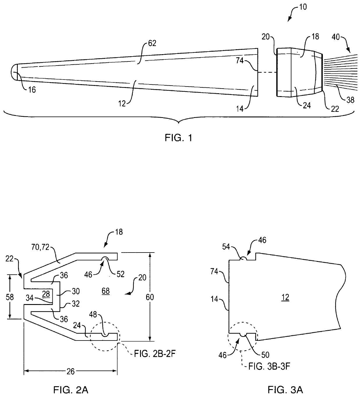
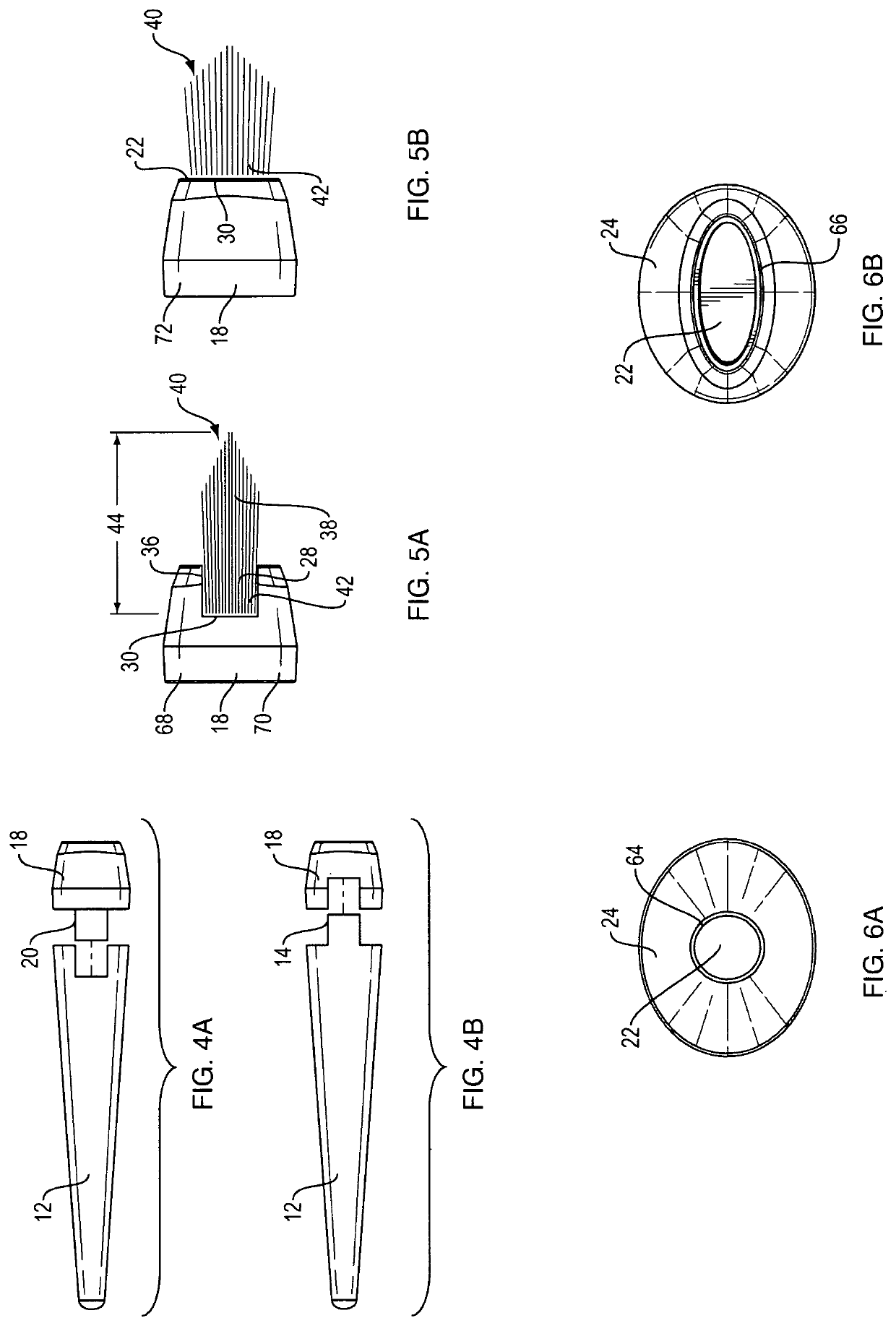
[0071]Referring first to FIG. 1, a side view of a makeup brush 10 of the present invention is provided. Makeup brush 10 includes handle 12 and ferrule 18. Handle 12 has ferrule end 14, where handle 12 connects to ferrule 18, and holding end 16, where a user will hold handle 12. Handle 12 preferably tapers 62 from ferrule end 14 to holding end 16 so that ferrule end 14 is wider than holding end 16. It is understood, however, that handle 12 may be uniform in width. Handle 12 may include cap 74 that covers ferrule end 14. Ferrule 18 includes ferrule inner end 20, which connects with ferrule end 14 of handle 12, and ferrule outer end 22, which faces away from handle 12. Ferrule 18 also includes ferrule body 24. Although shown more clearly in FIG. 2A, it is understood that ferrule body 24 has an interior 68 and well 28. Bristles 38 with bristle outer tips 40 extend from ferrule outer end 22. Throughout these FIGS., the discussion focuses on handle 12 and ferrule 18 being separate pieces ...


PUM

PropertyMeasurementUnit
lengthaaaaaaaaaa
sizesaaaaaaaaaa
perimeteraaaaaaaaaa

Abstract

The method for manufacturing a makeup brush includes: molding a ferrule and welding bristles to the ferrule. The ferrule includes a ferrule inner end; a ferrule outer end; a ferrule body; an interior; and a well. The well has a well base parallel to the ferrule outer end. The well base has an inner side and an outer side. The step of welding the bristles includes the steps of disposing the bristles in contact with the outer side of the well base and exposing the inner side of the well base to welding.

Description

CLAIM OF PRIORITY[0001]This application is a continuation in part of and claims the benefit of priority of co-pending U.S. patent application Ser. No. 16 / 139,099, filed on Sep. 24, 2018.FIELD OF THE INVENTION[0002]The present invention relates to cosmetic application technology, and in particular, to the manufacture of an improved makeup brush and makeup brush itself.BACKGROUND[0003]Brushes of varying types have almost universal utility, from industrial uses, to personal uses, to artistic endeavors, etc. The bristles of these various brushes may be made of a wide variety of materials, including hair, fur, synthetic filaments, etc. What all of these brushes have in common is that the bristles tend to fall out with use.[0004]Most brushes have a metal or plastic ferrule that hold the bristles in the brush. The bristles are glued or tied within the ferrule to hold them in place. Incomplete gluing during manufacture may cause the bristles to fall out of the brush during use. High-end bru...

Claims


Application Information

Patent Timeline
Patent Type & Authority Applications(United States)
IPC IPC(8): A46B9/02A46B3/02A46B7/04A46B3/06A45D33/00A45D34/04A45D40/26A46B5/02
CPCA46B9/021A46B3/02A46B7/042A46B3/06A46B2200/1046A45D34/04A45D40/26A46B5/02A45D33/00A46B3/10A46B2200/202A46D3/047A46B5/0095
Inventor GUNNESS, ANDREA
Owner LUMETIQUE
Why Eureka
Try Eureka