
Intra-oral scanning device, method of operating such a device and scanner system

a scanning device and scanner technology, applied in the field of intraoral scanning devices, can solve the problems of low reproducibility, low precision, and model space occupation, and achieve the effect of improving image quality or model quality and fast image collection and scanning process

Active Publication Date: 2021-05-06
DEVENTIV SP ZOO
View PDF0 Cites 2 Cited by
  • Summary
  • Abstract
  • Description
  • Claims
  • Application Information

AI Technical Summary

Benefits of technology

The patent describes an oral cavity scanning device that can accurately and conveniently scan a patient's mouth. The device has a pivot manipulator and a linear manipulator that allows for precise movement of the scanning head in a polar coordinate system, allowing for accurate scanning of the entire mouth. The device also collects data on the geometry and color of the mouth, improving the quality of the images and models generated, and can use the color information for diagnostic purposes and dental treatments. Overall, the device provides a convenient and accurate tool for automated scanning of the oral cavity.

Problems solved by technology

Inconveniences involved with such systems comprise that it is not easy to handle the materials which may stress the patient, cause low precision, introduce contaminations into the material used for the impression which may also be transferred to the gypsum model, that the model takes physical space and may be comparably costly and that the models need to be stored which requires space in a shelf at the dental office or lab.
They, typically have plural disadvantages such as a comparably low reproducibility, a comparably low accuracy and the like.
These disadvantages lead many dentists to select traditional impression tray for generating images and models of jaws or oral cavities rather than using scanning techniques.
However, most known solutions are still suffering with technical design drawback such as either not being optimal motorised or lacking the ability to be adjusted to the patient's given situation.
Since on the other hand the human mouth is rounded at its front or mesial end, arranging the mouthpiece inside the oral cavity is comparably inconvenient.
This leads the patient to perform compensation movements that may affect the accuracy of the scanning process.

Method used


Image

  • Intra-oral scanning device, method of operating such a device and scanner system
  • Intra-oral scanning device, method of operating such a device and scanner system
  • Intra-oral scanning device, method of operating such a device and scanner system

Examples


first embodiment

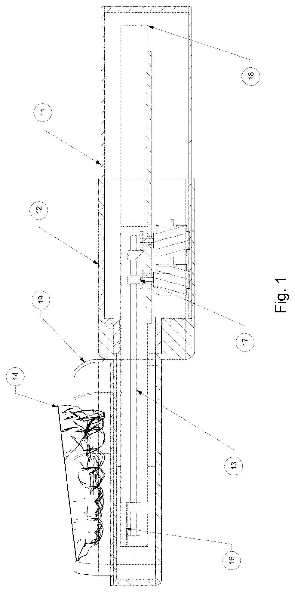
[0064]FIG. 1 shows an intra oral scanning device according to the invention. It comprises a main part 11 and a mouthpiece 12 with a cover section to protect the main part 11. It further comprises a scanning arm 13, which in operation or while scanning protrudes from the main part 11 and extends out of the main part 11 into a hollow interior of the mouthpiece 12. As indicated with the dotted line the scanning arm can also be positioned inside the main part 11 in a parking position 18. There it is protected in the main part 11 and the mouthpiece 12 can be removed or replaced or the like.

[0065]At one longitudinal end, the scanning arm 13 has a head portion 16 that is equipped with plural scanning sensors as signal collectors and light sources. The mouthpiece 12 is positioned in the mouth of a patient such that an upper jaw 14 resides on a top surface of the mouthpiece 12. The mouthpiece 12 has a buccal wing portion 19 that is positioned between the cheek and the teeth of the upper jaw ...

second embodiment

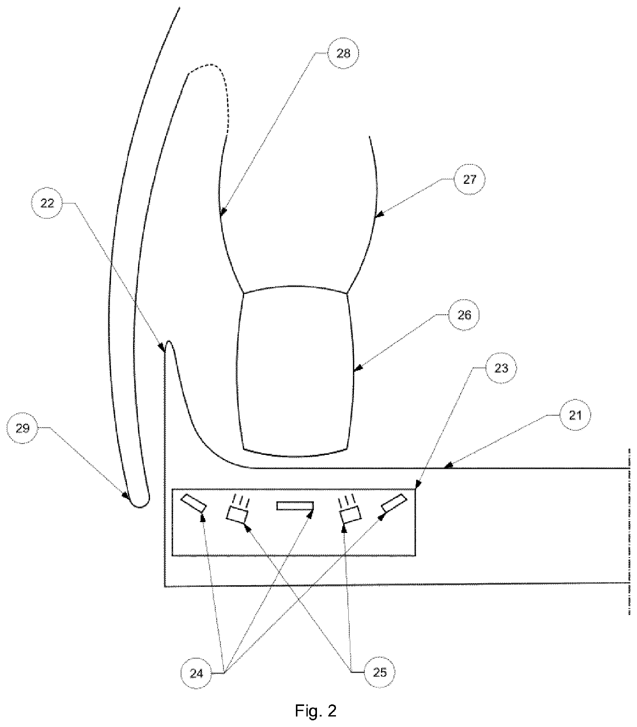
[0067]In FIG. 2 an intra-oral scanning device according to the invention is shown in operation. The device is similarly embodied as the first intra-oral scanning device described above. FIG. 2 shows a portion of a mouthpiece 21 arranged in an oral cavity of a patient below an upper jaw. The upper jaw comprises gingiva 27 and teeth 26, wherein the teeth 26 are adjacent to a transparent upper surface of the mouthpiece 21. The mouthpiece 21 has a wing portion 22 positioned between a vestibular side 28 of the gingiva 27 and a cheek 29 of the patient. By means of the wing portion 22, a distance or free space between the cheek 29 and a vestibular side of the upper jaw can be provided which allows for efficiently scanning the outer or vestibular side of the upper jaw as well.

[0068]A head portion 23 of a scanning arm of the second intra-oral scanning device is positioned inside a hollow interior of the mouthpiece and adjacent to the teeth 26 of the upper jaw. It is equipped with three scann...

third embodiment

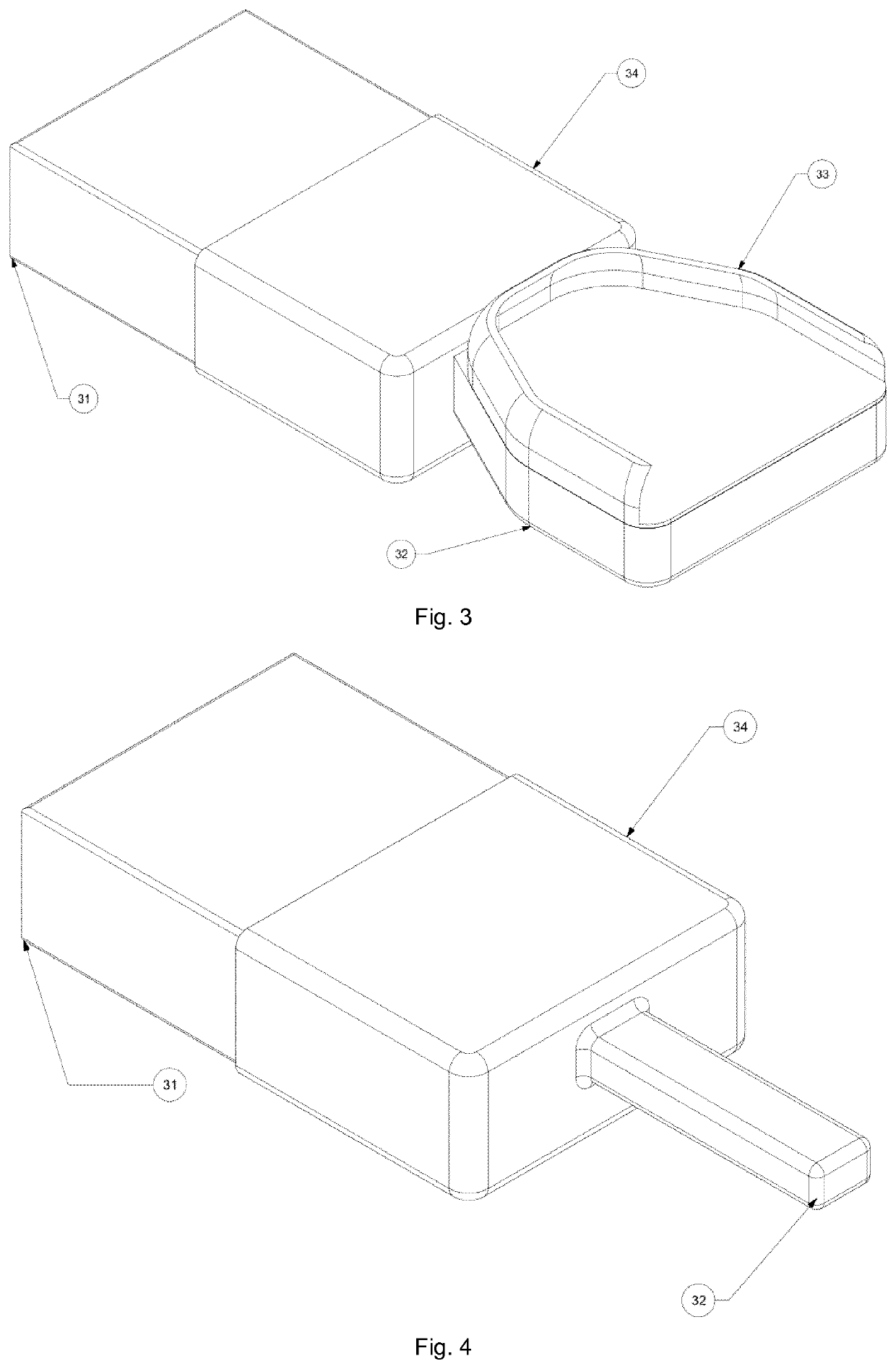
[0069]FIG. 3 shows an intra-oral scanning device. The device comprises a main part 31 and a mouthpiece 32, which has a wing portion 33. The main part 31 has a first mount structure and the mouthpiece 32 has a second mount structure 34. The first and second mount structures 34 are arranged to connect and release the mouthpiece 32 to and from the main part 31. In particular, the second mount structure 34 has a sleeve portion imposed over a section of the main part 31. Thereby, the sleeve portion on one hand holds the mouthpiece 32 on the main part 31 and on the other hand protects the main part 31 and particularly a transition between main part 31 and mouthpiece 32 where a scanning arm extends from the main part 31 into an interior of the mouthpiece 32.

[0070]In FIG. 4 and FIG. 5 a fourth embodiment and a fifth embodiment of intra-oral scanning devices are shown. The devices are identical to the intra-oral scanning device of FIG. 3, wherein the mouthpieces 32 are shaped differently. Th...


PUM


Abstract

An intra-oral scanning device includes a main part having a first mount structure, a scanning arm having at least one signal collector, a drive mechanism connected to the scanning arm to move a head portion of the scanning arm, and a mouthpiece positionable in an oral cavity. The mouthpiece has a hollow interior, an opening to access the hollow interior and a second mount structure. The scanning arm extends into the hollow interior when the first mount structure is connected to the second mount structure. The scanning arm is mounted to a pivot manipulator of the drive mechanism such that an axis of rotation of the pivot manipulator is essentially perpendicular to a longitudinal axis of the scanning arm. The scanning arm is mounted to a linear manipulator of the drive mechanism such that a distance between the pivot manipulator and the head portion of the scanning arm is modifiable.

Description

TECHNICAL FIELD[0001]The present invention relates to an intra-oral scanning device according to the preamble of independent claim 1 and more particularly to a scanner system and a method of operating an intra-oral scanning device.[0002]Such intra-oral scanning devices comprise (i) a main part having a first mount structure, (ii) a scanning arm having a head portion equipped with at least one scanning sensor, wherein the scanning arm is mounted to the main part and is arrangeable to protrude from the main part, (iii) a drive mechanism connected to the scanning arm to move the head portion of the scanning arm along an oral cavity of the patient, and (iv) a mouthpiece for being positioned in the oral cavity of a patient, having a hollow interior, an opening to access the hollow interior and a second mount structure corresponding to the first mount structure of the main part, wherein the scanning arm extends into the hollow interior of the mouthpiece when the first mount structure of t...

Claims


Application Information

Patent Timeline
IPC IPC(8): A61B5/00A61C13/00A61C7/00A61C9/00A61C19/05
CPCA61B5/0088A61C13/0004A61B5/0062A61C9/0053A61C19/05A61C7/002A61C19/04A61B1/24
Inventor BINKOWSKI, MARCIN
Owner DEVENTIV SP ZOO
Learn More