Liquid crystal display device

a liquid crystal display and display device technology, applied in non-linear optics, instruments, optics, etc., can solve problems such as difficulty in inhibiting internal reflection throughout the whole wavelength range of visible light, low contrast, and problem occurred

Active Publication Date: 2021-05-06
SHARP KK
View PDF0 Cites 0 Cited by
  • Summary
  • Abstract
  • Description
  • Claims
  • Application Information

AI Technical Summary

Benefits of technology

The present invention is about a liquid crystal display that can show proper colors without color distortion, and prevent internal reflection. This ensures that the display is good quality.

Problems solved by technology

However, in a liquid crystal display panel in related art, contrast may lower after a heat resistance test.
Then, the inventors used a highly durable retardation plate but found that it was difficult to inhibit internal reflection throughout the whole wavelength range of visible light and a screen was colored in a case of black display.
To handle this situation, the inventors had an investigation on use of a more yellowish backlight than related art but found that another problem occurred: white display, which was basically desirably achromatic, was colored in yellow.
To handle this situation, the inventors had an investigation on reduction in blueness of black display by using a more yellowish backlight than related art but found that another problem occurred: white display, which was basically desirably achromatic, was colored in yellow.

Method used


Image

  • Liquid crystal display device
  • Liquid crystal display device
  • Liquid crystal display device

Examples


first embodiment

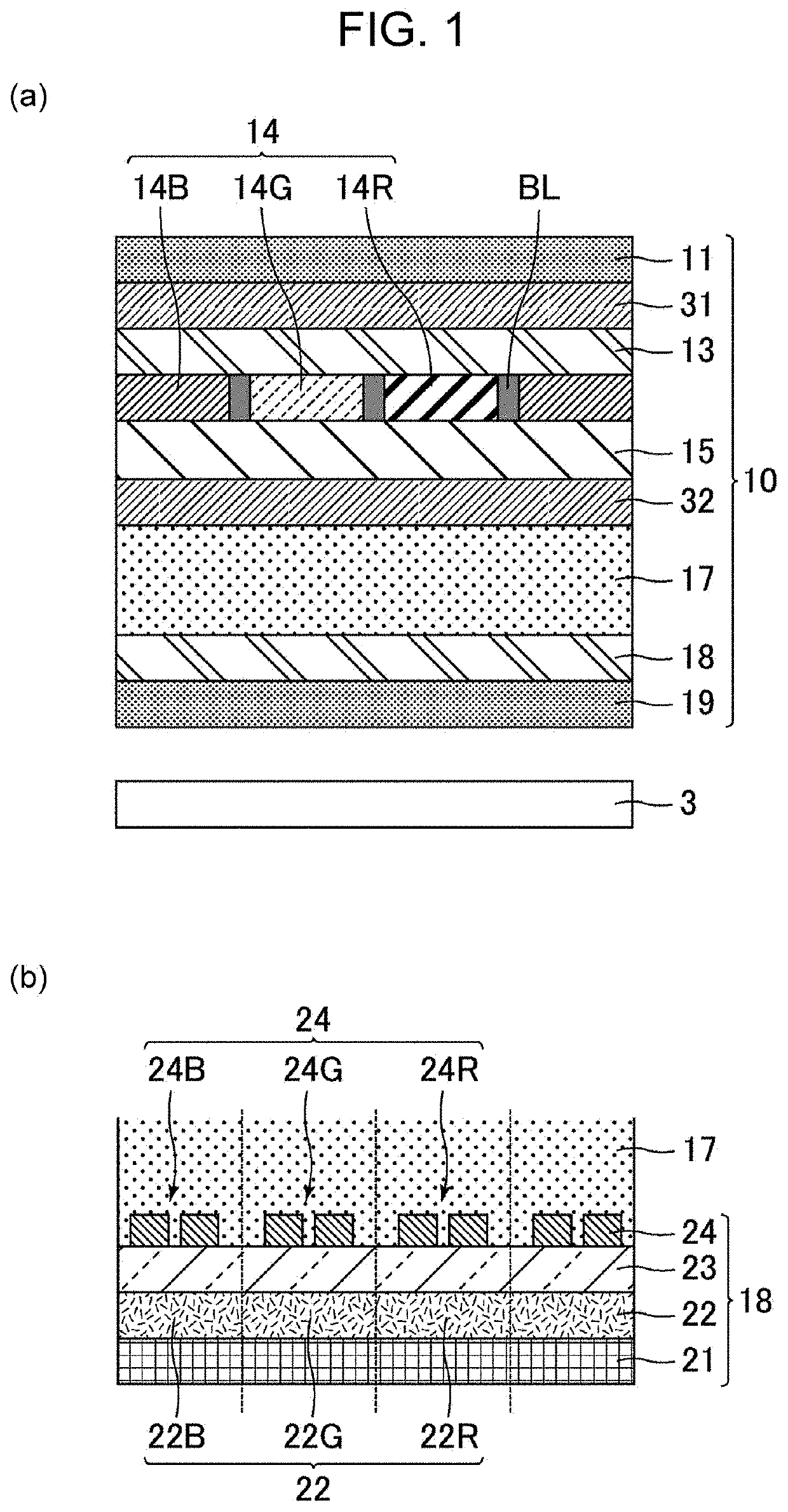
[0035]FIG. 1(a) is a cross-sectional schematic diagram that illustrates a liquid crystal display device of a first embodiment, and FIG. 1(b) is a cross-sectional schematic diagram that illustrates one example of a configuration of a second substrate. As illustrated in FIG. 1(a), the liquid crystal display device of the first embodiment includes a backlight 3 and a liquid crystal display panel 10. The backlight 3 is positioned on a back surface side, and the liquid crystal display panel 10 is positioned on an observation surface side. The light amount, which is transmitted through the liquid crystal display panel 10, of the light emitted by the backlight 3 is controlled by an applied voltage to a liquid crystal layer 17 provided in the liquid crystal display panel 10.

[0036]The type of the backlight 3 is not particularly limited. For example, an edge light type, a direct type, and so forth may be raised. The kind of a light source of the backlight 3 is not particularly limited. For ex...

example 1

PRACTICAL EXAMPLE 1

[0118]In practical example 1, the out-cell λ / 4 plate 31 formed of a different material from the in-cell λ / 4 plate 32 is used, and in a liquid crystal display device that uses the 0.5 times yellow backlight, the applied voltages to the B sub-pixel, the G sub-pixel, and the R sub-pixel in white display are respectively set to 4.4 V, 2.3 V, and 2.3 V.

examples 2 and 3

PRACTICAL EXAMPLES 2 AND 3

[0119]A liquid crystal display device of practical example 2 is the same as the liquid crystal display device of practical example 1 except that each of the applied voltages to the G sub-pixel and the R sub-pixel is changed to 2.5 V. A liquid crystal display device of practical example 3 is the same as the liquid crystal display device of practical example 1 except that each of the applied voltages to the G sub-pixel and the R sub-pixel is changed to 2.7 V.


PUM

PropertyMeasurementUnit
wavelengthaaaaaaaaaa

Abstract

The present invention provides a liquid crystal display device of a transverse electric field mode that may inhibit internal reflection and realize proper black display to which coloring does not occur. The present invention provides a liquid crystal display device including a first linear polarizer, a first λ / 4 retardation layer, a first substrate, a second λ / 4 retardation layer configured with a different material from the first λ / 4 retardation layer, a liquid crystal layer that contains liquid crystals which are horizontally aligned in a case where no voltage is applied, plural electrode pairs that generate a transverse electric field in the liquid crystal layer by a voltage being applied, a second substrate, a second linear polarizer, and a backlight. In a case where a color of light emitted from the backlight is expressed by using chromaticity coordinates (x, y) of an XYZ color system, both of x and y are 0.32 or greater. The plural electrode pairs include a red electrode pair arranged in a red sub-pixel, a green electrode pair arranged in a green sub-pixel, and a blue electrode pair arranged in a blue sub-pixel. A white display applied voltage of the blue electrode pair is different from the white display applied voltage of the red electrode pair and the white display applied voltage of the green electrode pair.

Description

TECHNICAL FIELD[0001]The present invention relates to a liquid crystal display device, more specifically to a liquid crystal display device of a transverse electric field mode.BACKGROUND ART[0002]As driving modes of liquid crystals, transverse electric field modes such as an in-plane switching (IPS) mode and a fringe field switching (FFS) mode have widely been used. A liquid crystal display panel is used not only for a television but also widely used for various purposes of use such as a laptop PC, a tablet PC, a smartphone, and a car navigation system and may be used under strong external light as in an outdoor environment. Thus, a liquid crystal display device of the IPS mode has been suggested which may inhibit reflection of external light, reduce light transmittance in a case of black display, and obtain proper image quality even in cases of use in both of indoor and outdoor environments (for example, see PTL 1).CITATION LISTPatent Literature[0003]PTL 1: Japanese Unexamined Pate...

Claims


Application Information

Patent Timeline
Patent Type & Authority Applications(United States)
IPC IPC(8): G02F1/1343G02F1/1335G02F1/13363G02F1/1337
CPCG02F1/134363G02F1/133528G02F1/133638G02F1/133633G02F2202/022G02F2413/13G02F2413/02G02F2413/06G02F1/133738
Inventor SAKAI, AKIRAKAWAHIRA, YUICHIMURATA, KOJIHASEGAWA, MASAHIROKOIDE, TAKAKONAKAMURA, KOZOMINOURA, KIYOSHI
Owner SHARP KK
Why Eureka
Try Eureka