Tire segment model and a method of making a tire mold segment

a tire segment and tire mold technology, applied in the field of 3dprinted tire segment models, can solve the problems of high cost, inability to meet in all cases accuracy and quality expectations, and large turnaround time of molds, and achieve the effects of improving mechanical stability, high stability, and easy handling of models

Pending Publication Date: 2021-05-13
THE GOODYEAR TIRE & RUBBER CO
View PDF11 Cites 0 Cited by
  • Summary
  • Abstract
  • Description
  • Claims
  • Application Information

AI Technical Summary

Benefits of technology

[0016]In still another embodiment, the tire segment model has a 3D-printed supporting structure extending at least below the tread. The supporting structure may have the purpose of giving the segment model a better mechanical stability and ease handling of the model. For instance, the supporting structure may be a closed cell structure or a three-dimensional grid. Such structures can provide relatively high stability requiring a limited amount of material at limited weight. In addition, or alternatively, a support structure can also beneficially serve as a substrate or base on which the tread pattern of the model is printed. Thus, the support structure could be 3D-printed or otherwise manufactured, such a molded. Providing a support structure before printing the tread could further decrease the timing for printing the tire segment model.
[0017]In still another embodiment, the polymer is chosen from a group of thermoplastic materials. The thermoplastic material used is typically an acrylonitrile-butadiene-styrene triblock polymer (ABS), an acrylonitrile-styrene-acrylonitrile triblock polymer (ASA), a poly(lactic acid) (PLA), a polycarbonate (PC), a polystyrene (PS), a high impact polystyrene (HIPS), a polycaprolactone (PCL), or a polyamide (nylon). Blends of acrylonitrile-butadiene-styrene triblock polymers (ABS) and polycarbonates (PC) can be used in applications where a high level of strength and durability is required. Such blends are typically comprised of 35 weight percent to 65 weight percent of the ABS and 35 weight percent to 65 weight percent of the PC. To attain a higher level of strength and durability glass filled PC can also be used. The polyamide used will typically be selected from nylon-6,6, nylon-4,6. nylon-6,9, nylon-6,10, nylon 6.12, nylon-6, nylon-11, or nylon-12. Glass filled nylons, such as glass filled nylon-12, can also be used.
[0018]ABS has the advantage of good overall mechanical properties; however it suffers from relatively large volumetric shrinkage and the generation of unpleasant odors. Accordingly, the generation of potentially toxic degradation products during printing makes ABS a less suitable option for used in printers that do not have a heated build envelope and an effective mechanism to eliminate the odor and toxic degradation products. PLA, on the other hand, has less volumetric shrinkage which allows it to be printed properly even without a heated build envelope. It generates no unpleasant odor during printing, and the main degradation product is lactic acid which poses minimal health risk to personnel. However, PLA suffers from a number of drawbacks, including poor impact strength and a low softening temperature.
[0019]In general, multiple known 3D printing (or in other words additive manufacturing) methods and equipment could be used. However, in a preferred embodiment, stereolithography (also known as SL or SLA) may be used. SLA is a photopolymerization method, typically involving a cure of a photopolymer by means of a laser. One advantage of using this technology in an embodiment of the present invention is that this method allows for achieving high quality including an advanced accuracy and finish, all at relatively high speed.

Problems solved by technology

Making such molds typically involves a significant turnaround time to ensure the desired accuracy and because a high level of manual labor is normally required.
However, it has been found that such processes are expensive and do not meet in all cases accuracy and quality expectations.
Also, fine structures are often not as reproducible as desired.
However, such milling processes often have the disadvantage of limiting the tire tread design to certain shapes because milling tools frequently cannot create all complex three-dimensional (3D) structures which may be desired in tire molds.

Method used


Image

  • Tire segment model and a method of making a tire mold segment
  • Tire segment model and a method of making a tire mold segment
  • Tire segment model and a method of making a tire mold segment

Examples


Embodiment Construction

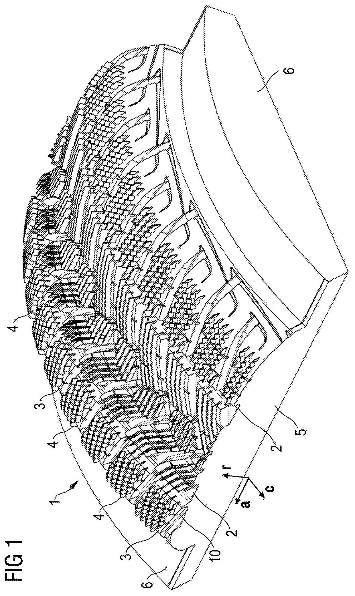
[0035]FIG. 1 shows a schematic perspective view of a tire segment model 1 in accordance with a preferred embodiment of the present invention. The tire segment model 1 comprises a tread portion 10 having a plurality of grooves 2 and a plurality of tread blocks 3. The tire segment model 1 further comprises blades 4 which extend from the radially outer surface of the tread blocks 3. The tread 10 may be arranged on a support portion 5 which may have also extensions 6 on both lateral side of the tread 10, which may facilitate handling of the tire segment model 1. The axial direction a, the circumferential direction c and the radial direction r are indicated, in the same sense as common for the description of tire symmetries. In accordance with this invention, the tire segment model 1 is made completely by 3D-printed.

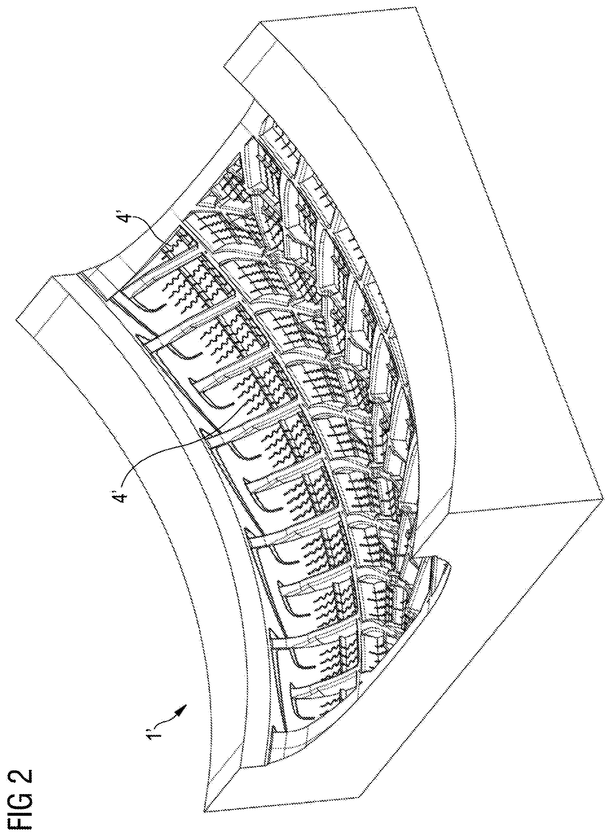
[0036]FIG. 2 shows a negative cast 1′ made of rubber material and formed with the positive tire tread segment model 1 of FIG. 1. As visible in FIG. 2, the negative cast 1′ ha...


PUM

PropertyMeasurementUnit
heightaaaaaaaaaa
heightaaaaaaaaaa
melting pointaaaaaaaaaa

Abstract

The present invention is directed to a 3D-printed tire segment model having a tread portion comprising a plurality of grooves, ribs and/or tread blocks, and a plurality of blades extending out of the ribs and/or tread blocks, wherein the tire segment model is made of a 3D-printed polymer. Moreover, the present invention is drawn to a method of making a tire mold segment, including the step of 3D-printing the above tire segment model with a polymer.

Description

[0001]This application claims benefit of U.S. Provisional Patent Application Ser. No. 62 / 932,081, filed on Nov. 7, 2019. The teachings of U.S. Provisional Patent Application Ser. No. 62 / 932,081 are incorporated herein by reference in their entirety.FIELD OF THE INVENTION[0002]This invention relates to a 3D-printed tire segment model having a tread portion comprising a plurality of grooves, ribs and / or tread blocks, and a plurality of blades extending out of the ribs and / or tread blocks, wherein the model is made of a 3D-printed polymer. Moreover, the present invention is drawn to a method of making a tire mold segment, including the step of 3D-printing the tire segment model with a polymer.BACKGROUND OF THE INVENTION[0003]Manufacturing of tire mold segments for molding tires is a crucial task in the tire manufacturing process. Molds must fully meet specifications as typically thousands of tires are made with a single mold. For these reasons, mold manufacturing is carried out with gr...

Claims


Application Information

Patent Timeline
Patent Type & Authority Applications(United States)
IPC IPC(8): B29C33/38B29D30/06B33Y10/00B33Y80/00
CPCB29C33/3842B29D30/0606B33Y10/00B29K2905/12B29D2030/0613B29K2905/02B33Y80/00B29C33/42B29C33/424B29C64/245B29C64/135B33Y30/00B29L2030/002B29D2030/0612B29D30/0662
Inventor LAURENT, DAVID CHARLES JACQUES ROBERTSANDER, JEAN-PHILIPPE ALOYSE HENRIREGNIER, ANTOINE FRANCOIS
Owner THE GOODYEAR TIRE & RUBBER CO
Why Eureka
Try Eureka