An anchoring device for a railway rail fastening assembly

Pending Publication Date: 2021-05-20
PANDROL LTD
View PDF7 Cites 0 Cited by
  • Summary
  • Abstract
  • Description
  • Claims
  • Application Information

AI Technical Summary

Benefits of technology

[0026]The anchoring device may further comprise at least one catch feature configured to hold the clip captive when the clip is in an intermediate

Problems solved by technology

Although quite possible, this more complex joint line is a disadvantage in production.
However, such an anchoring device is difficult to cast due to the

Method used


Image

  • An anchoring device for a railway rail fastening assembly
  • An anchoring device for a railway rail fastening assembly
  • An anchoring device for a railway rail fastening assembly

Examples


Embodiment Construction

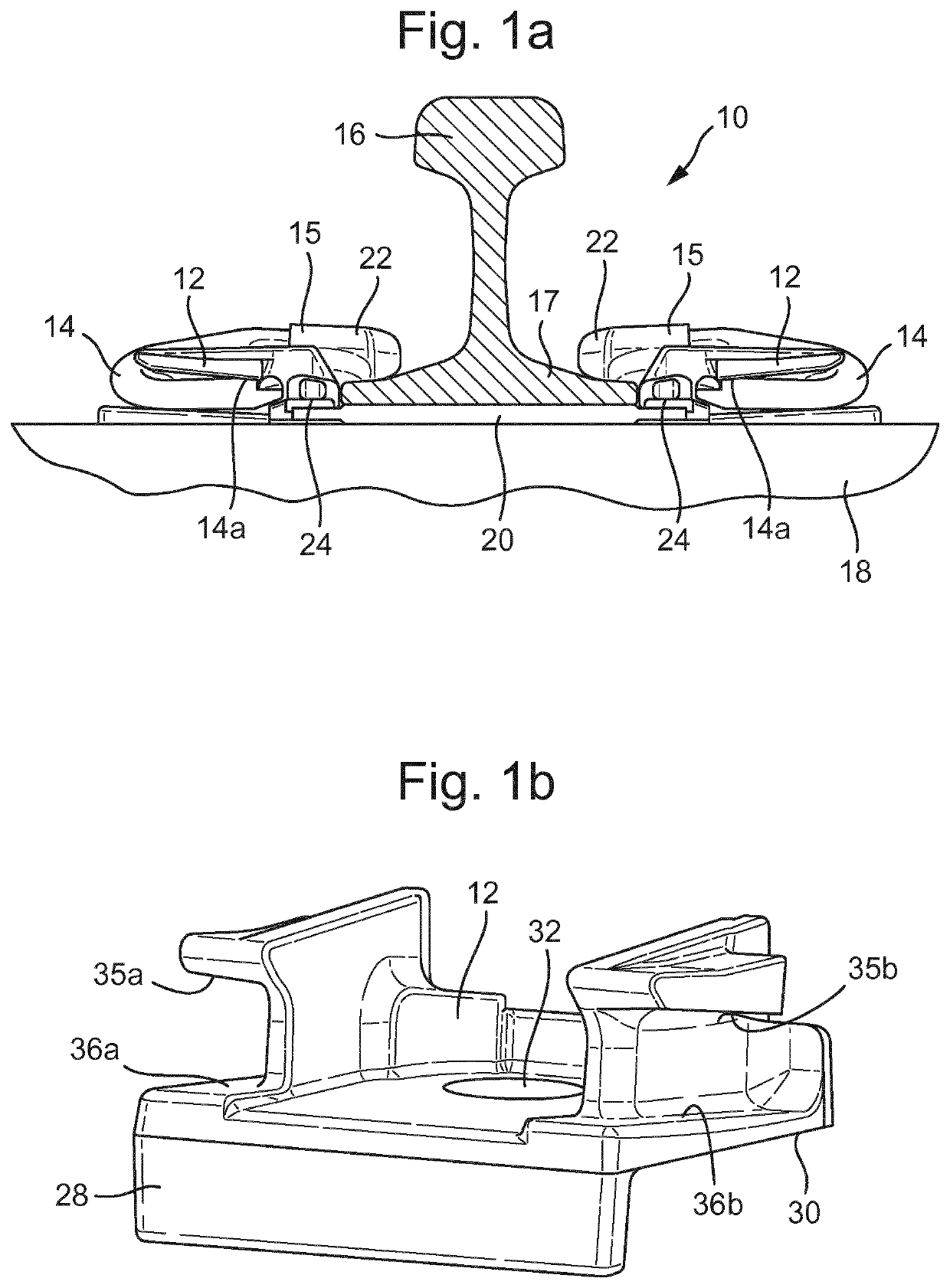
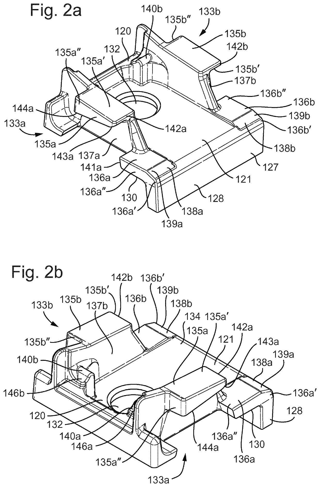
[0043]With reference to FIG. 2, an anchoring device 120, e.g. a shoulder, according to a first arrangement of the present disclosure may form part of a railway rail fastening assembly 10 as depicted in FIG. 1a. In other words, the anchoring device 120 may replace the anchoring device 12 depicted in FIG. 1a. As such, the anchoring device 120 is configured to receive a railway rail fastening clip 14 and may be connected to an underlying foundation 18, such as a railway sleeper or slab. Respective anchoring devices 120 are provided on either side of a railway rail 16 for retaining clips 14 which bear on a rail foot 17. The clip 14 secures the railway rail 16 to the underlying foundation by virtue of forces exerted by the clip on the anchoring device 12 and the rail 16.

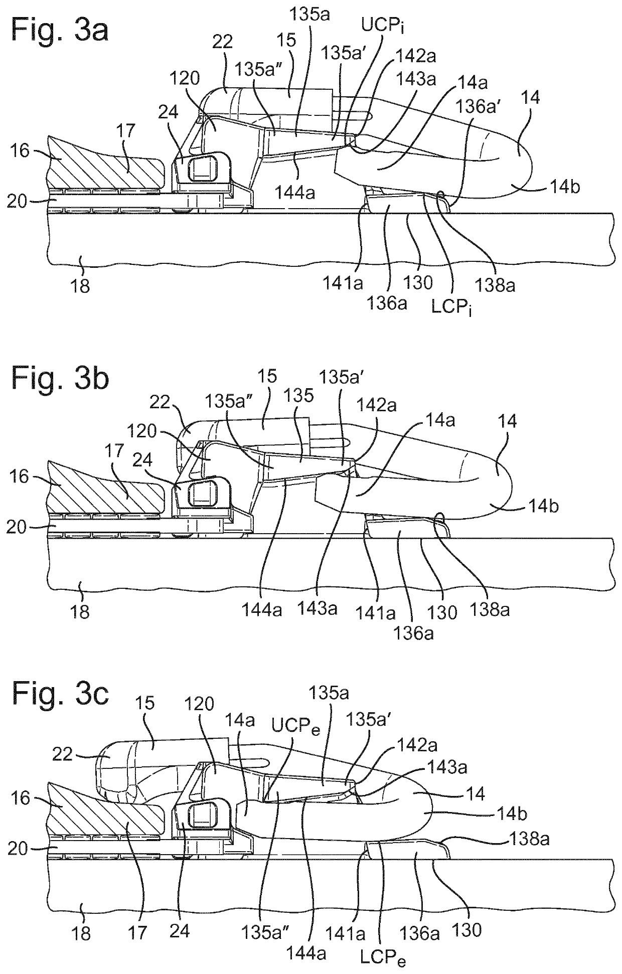
[0044]The clip 14 has first and second leg portions 14a and a rail-bearing “toe” portion 15 therebetween. The clip 14 may be M-shaped, e.g. when viewed from above and when installed. The clip 14 may be configured such tha...


PUM

PropertyMeasurementUnit
Angleaaaaaaaaaa
Widthaaaaaaaaaa

Abstract

An anchoring device for use in retaining a railway rail fastening clip having first and second leg portions and a rail-bearing portion therebetween. The anchoring device includes a base member, an opening in the base member configured to receive a fastening component for fastening the anchoring device to an underlying foundation, and first and second clip-retaining sides extending from said base member with the first clip-retaining side being spaced apart from the second clip-retaining side so as to define a space therebetween for receiving the rail-bearing portion of the clip. Each clip-retaining side comprising upper and lower clip contact walls defining a passageway for receiving one of the leg portions, wherein the leg portions contact the clip contact walls of the respective clip-retaining sides as the clip moves from a wedged position towards an engaged position where the rail-bearing portion of the clip bears on the rail.

Description

BACKGROUND[0001]In the documents WO93 / 12294, WO93 / 12295 and WO93 / 12296, the present applicants disclosed a railway rail fastening system in which a rail fastening clip is driven laterally onto the rail and can be held in a clip anchoring device (shoulder) in a “pre-assembly” or “parked” position in which the toe portion of the clip does not bear on the rail. This enables railway sleepers to be preloaded at the factory with clips which are held captive in the pre-assembly position such that when the sleepers are delivered to site the clips can simply be driven home once the rail is in place. In addition, when maintenance of the rail is subsequently required, the clip can be driven off the rail back into the pre-assembly position, so complete withdrawal of the clip from the shoulder is not necessary. Such clips are sometimes known as “switch-on / switch-off” clips.[0002]Anchoring devices for retaining switch-on / switch-off clips are typically made by casting. Features on the casting coop...

Claims


Application Information

Patent Timeline
IPC IPC(8): E01B9/48
CPCE01B9/483E01B9/303E01B13/02B23P15/20E01B9/30E01B9/34E01B9/48
Inventor PORRILL, JOHN PHILLIPSPENCER, JOHN DAVIDCOX, STEPHEN JOHNKEAST, BRENTONHARKNESS, STEVENLEA, CHRIS
Owner PANDROL LTD
Why Eureka
Try Eureka