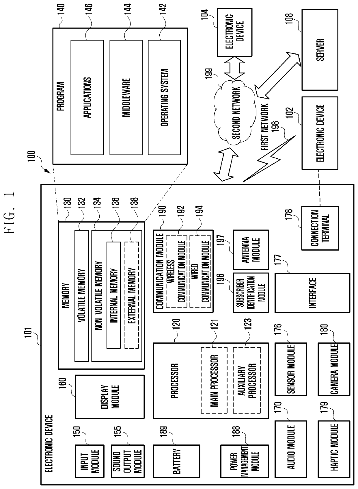
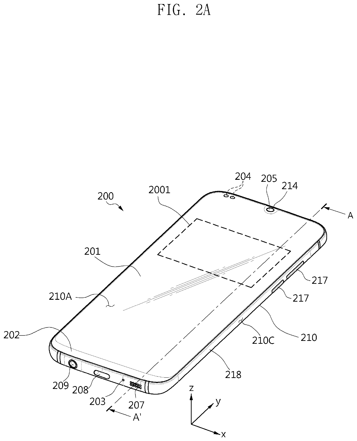
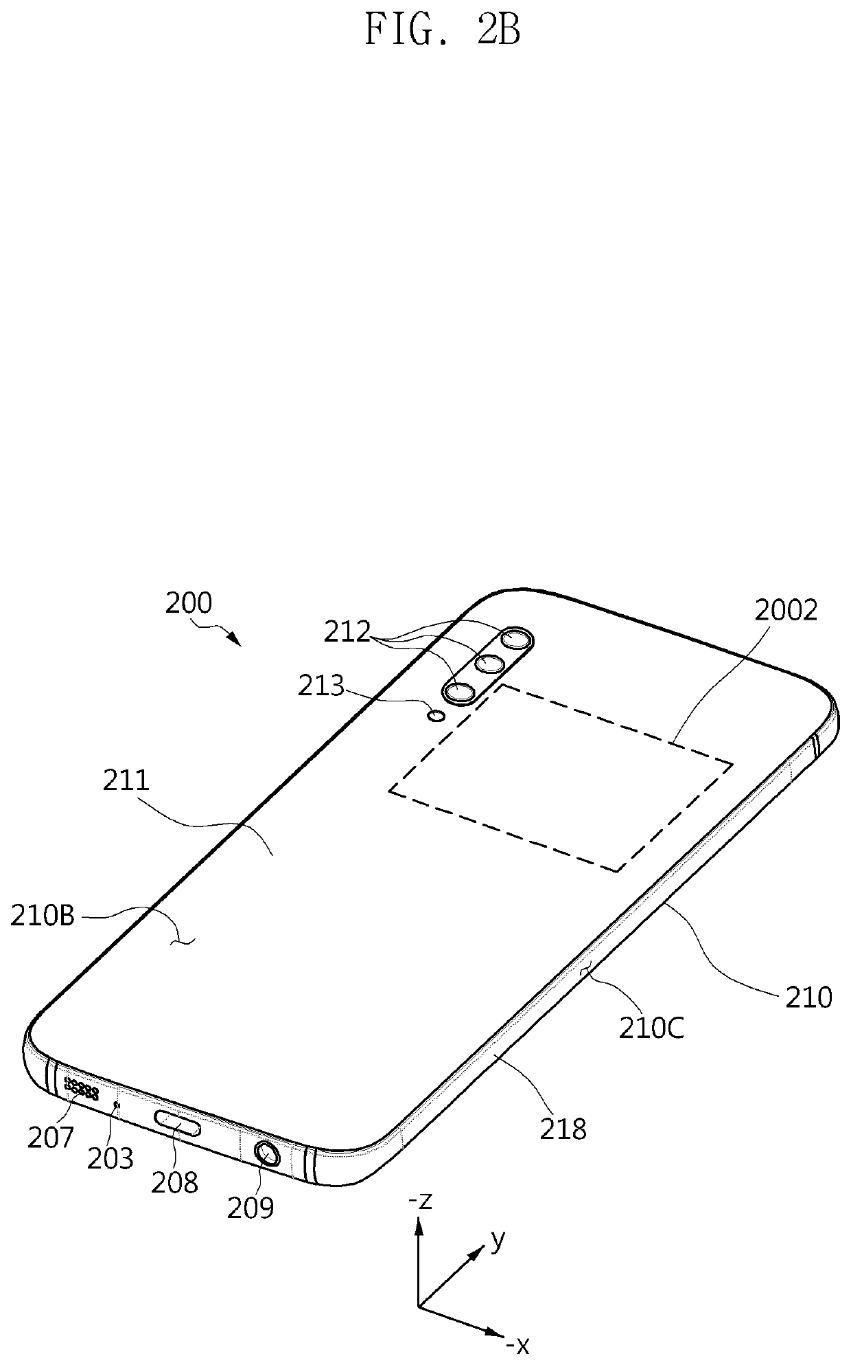
Electronic device including antenna
a technology of electronic devices and antennas, applied in the direction of near-field devices for reading/writing/interrogation/identification systems, devices with near-field communication, can solve the problems of user attempts to change the electronic device from the folded state, inconvenience of switching the electronic device, etc., to reduce the limitation of the nfc recognition range, slim the electronic device, and improve the user experience. the effect of the rang
- Summary
- Abstract
- Description
- Claims
- Application Information
AI Technical Summary
Benefits of technology
Problems solved by technology
Method used
Image

Examples
Embodiment Construction
[0048]The following description is made with reference to the accompanying drawings and is provided to assist in an understanding of various embodiments of the disclosure. It includes various specific details to assist in that understanding but these are to be regarded merely as examples, and are not intended to be limiting. Accordingly, those of ordinary skill in the art will recognize that various changes and modifications of the various example embodiments described herein can be made without departing from the scope and spirit of the disclosure. In addition, descriptions of well-known functions and constructions may be omitted for clarity and conciseness.
[0049]The terms and words used in the following description and claims are not limited to the bibliographical meanings, but, are merely used to enable a clear and consistent understanding of the disclosure. Accordingly, it should be apparent to those skilled in the art that the following description of various example embodiment...
PUM
 Abstract
Description
Claims
Application Information