Threshing/Separating Device Having Tined Accelerator and/or Axial Rotor System

a technology of axial rotor and threshing/separating device, which is applied in the direction of digger harvester, agriculture, agricultural tools and machines, etc., can solve the problems of incompatibility with other styles of feed cylinder, inefficient handling of peanuts or similar root types, and inability to meet the needs of the user, so as to achieve gentle and efficient handling, reduce damage, and improve the effect of handling

Pending Publication Date: 2021-06-03
AMADAS INDS
View PDF0 Cites 0 Cited by
  • Summary
  • Abstract
  • Description
  • Claims
  • Application Information

AI Technical Summary

Benefits of technology

[0013]A spring tined accelerator cylinder is far superior in its ability to handle foreign materials all while being gentle and efficient enough to handle delicate peanut pods while minimizing any damaging affects to the pods themselves. The use of double torsional spring tine cylinder elements on a spring tined accelerator cylinder engage the crop mat through a piercing action which allows the harvester to efficiently and effectively propel the crop mat for further processing. Along the harvesting process, if an inconsistent (light or heavy) crop mat is ingested by the machine, the double torsional spring tine cylinder elements or double torsional spring tine rotor elements are able to apply progressive force to the crop mat without damage and continue to propel the crop mat without impeding flow. Being able to propel the crop mat through a harvester without machine or crop damage, is critical to a well-designed machine.
[0014]The accelerator cylinders convey the peanut or other crop mats toward and / or into one or more spring tined axial rotors. The spring tined axial rotors provide improved threshing and separating where the peanut pods are detached from and then removed from the crop mat. When utilizing more than one axial rotor, a symmetrical inverse of the primary rotor is often employed. In multi-axial rotor configurations, the longitudinal axes of the rotors often lie on the same plane and are parallel with respect to one another. Another unique aspect of an axial rotor is its inlet, which is distinct in it is are conical in shape and has auger styled flighting segments which aids in feeding the crop mat into the rotor from one or more spring tined accelerator cylinder.
[0015]Axial spring threshing elements are attached or coupled to the perimeter of the rotors. The spring tined axial rotor utilizes one or more double torsional spring tine rotor elements with various spacing and patterns along a perimeter of the spring tined axial rotor. Unlike a rigid threshing element, a double torsional spring tine rotor element allows flexibility in the harvesting process when a progressive force needs to be applied to the crop mat. Without double torsional spring tine cylinder elements or double torsional spring tine rotor elements, damage to a conventional styled system using rigid elements is imminent. During the threshing operation, it is important for the separating elements to keep materials, especially foreign materials, moving through the harvester so they can be properly processed and expelled. Failure to maintain a positive flow of material is likely to cause crop and machine damage, subsequently requiring the harvester to be shut down, inspected, and / or repaired. If a traditional harvester, one that employs rigid elements sustains failure to its rigid elements, then the materials would stall, causing damage to this area of the device. In contrast, the double torsional spring tine cylinder elements and double torsional spring tine rotor elements of the present disclosure, will flex around materials as needed while still imparting positive movement to the materials, then allowing the double torsional cylinder elements and double torsional spring tine rotor elements to return to their natural position, undamaged. This greatly minimizes harvest downtime and / or machine damage.
[0016]The spring rate, placement, and configuration of the double torsional spring tine cylinder elements and double torsional spring tine rotor elements provides improved harvesting benefits. In various exemplary, non-limiting embodiments, the double torsional spring tine rotor elements are oriented in a pattern or series of patterns along the perimeter or portions of the perimeter of the main rotor core. The pattern of the double torsional spring tine rotor elements are based on the direction of rotation of the rotor. The position, spacing, and geometry of the double torsional spring tine rotor elements are unique in that they allow a more natural flow or movement of the crop mat along the rotor's axis.

Problems solved by technology

The use of other styles of feed cylinders are incompatible, or at the very least, greatly inefficient in handling peanuts or similar root type crops.

Method used


Image

  • Threshing/Separating Device Having Tined Accelerator and/or Axial Rotor System
  • Threshing/Separating Device Having Tined Accelerator and/or Axial Rotor System
  • Threshing/Separating Device Having Tined Accelerator and/or Axial Rotor System

Examples


Embodiment Construction

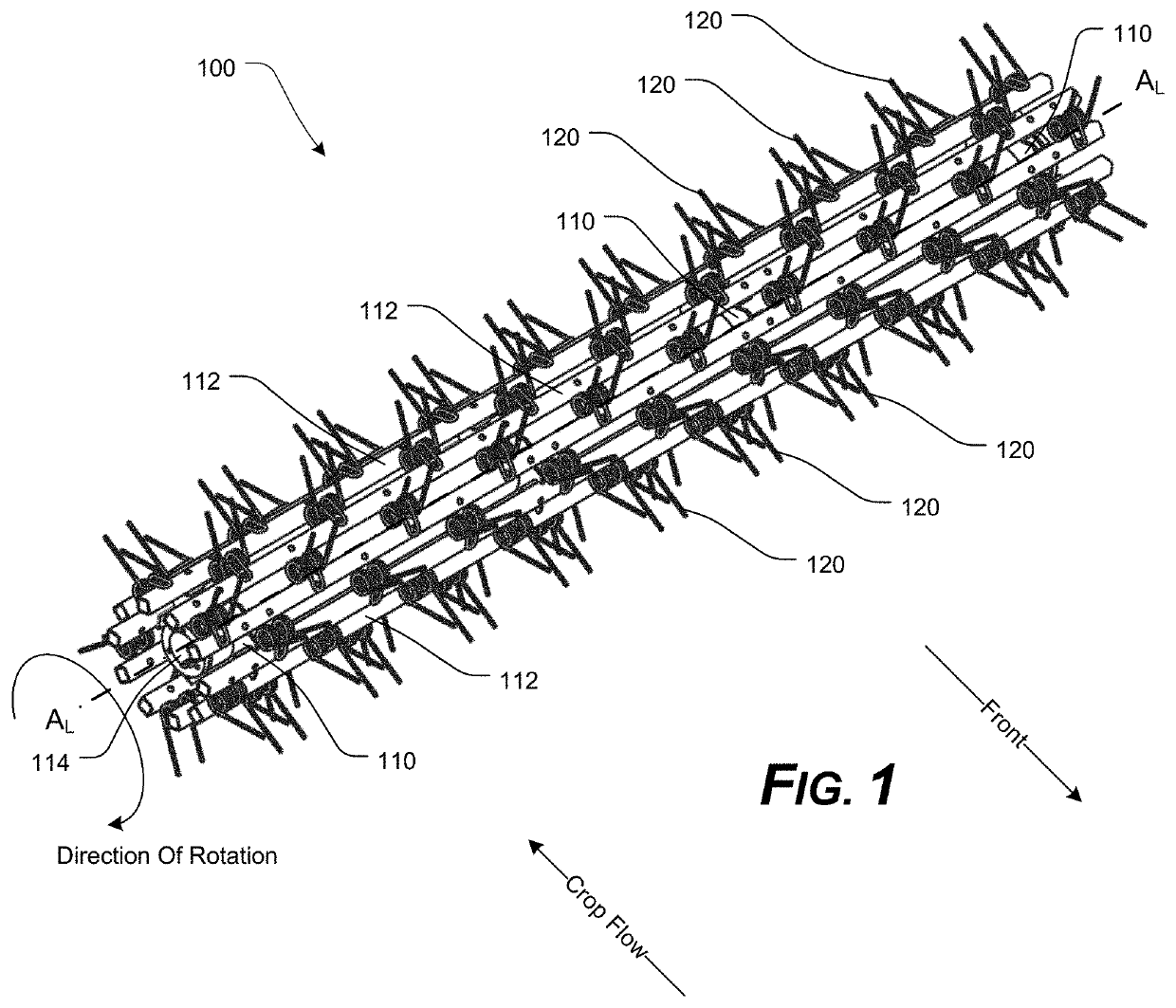
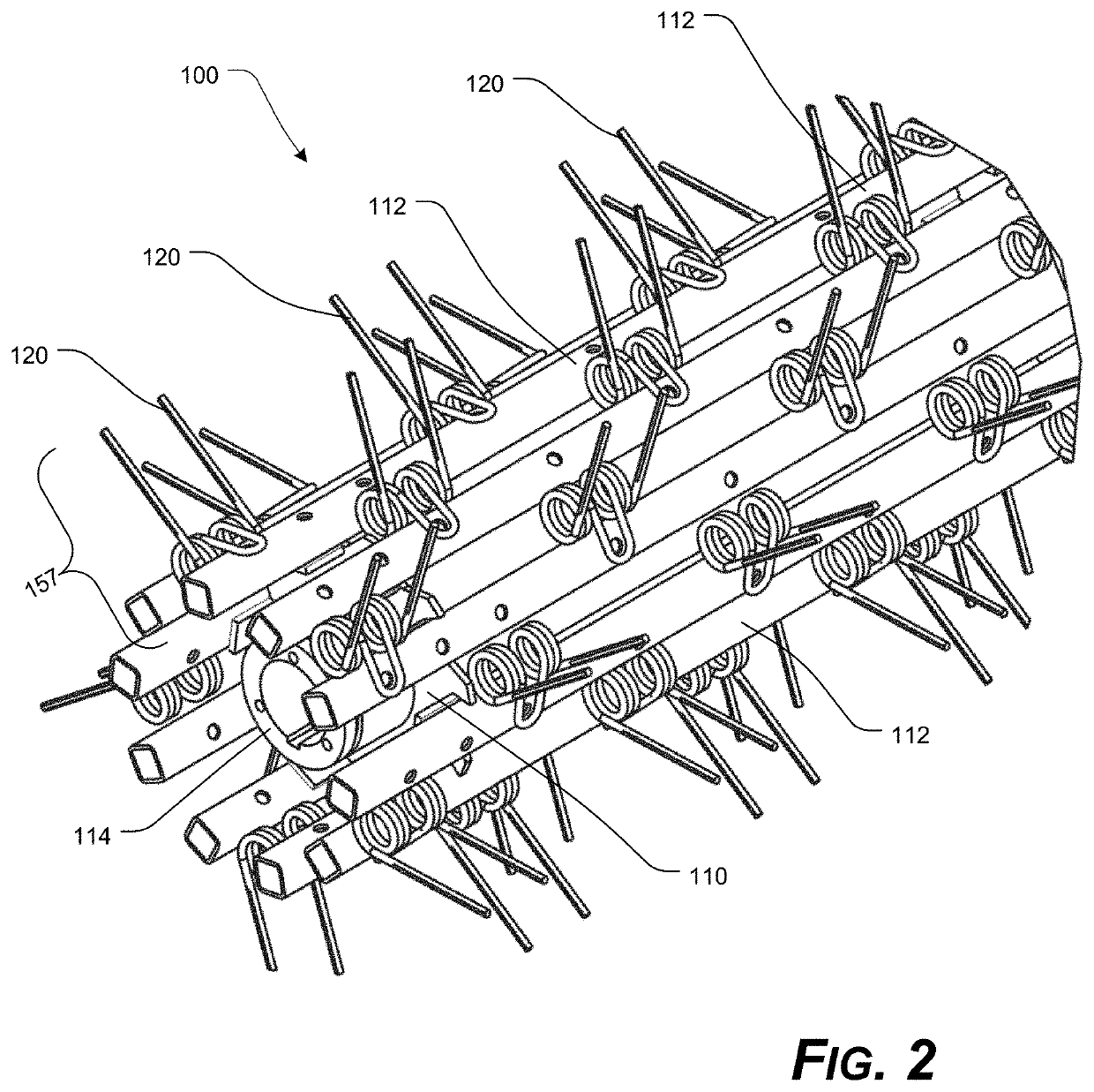
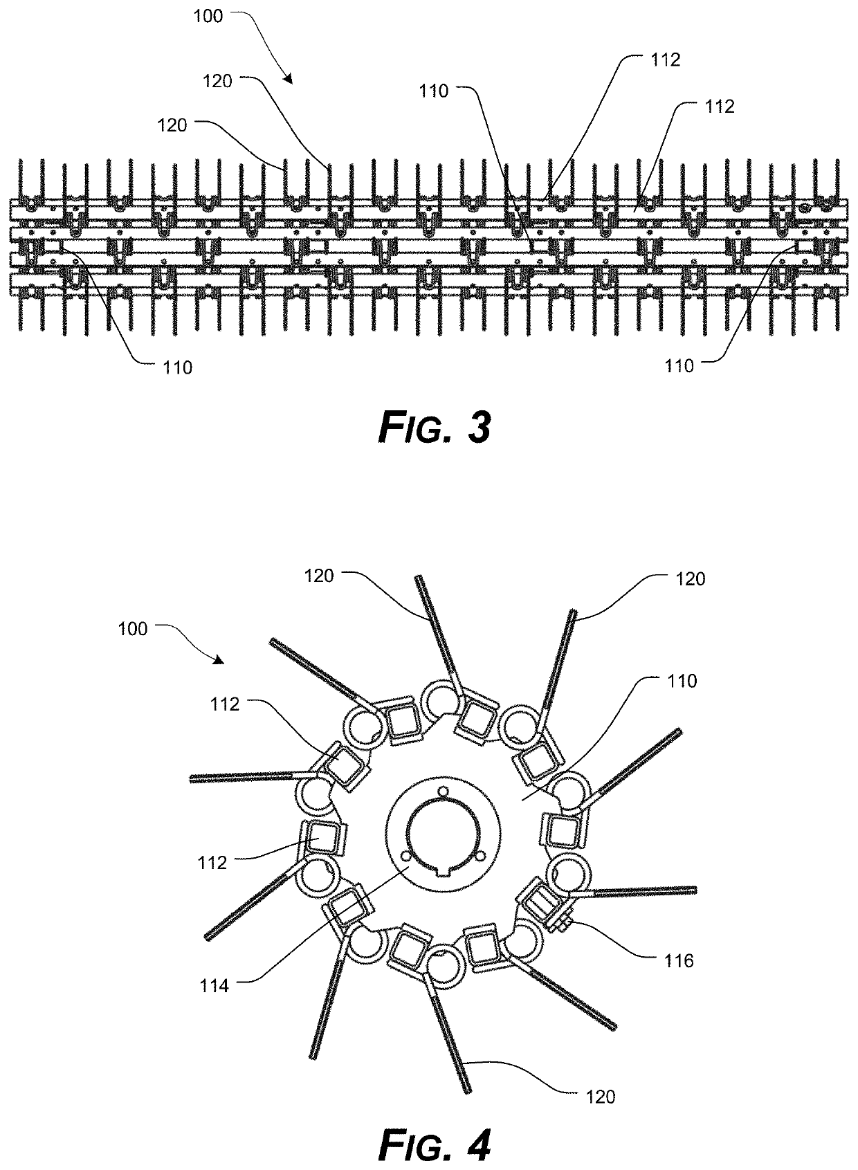
[0051]For simplicity and clarification, the design factors and operating principles of the axial threshing / separating components and / or systems according to the presently disclosed systems, methods, and / or apparatuses are explained with reference to various exemplary embodiments of axial threshing / separating components and / or systems according to the presently disclosed systems, methods, and / or apparatuses. The basic explanation of the design factors and operating principles of the axial threshing / separating components and / or systems is applicable for the understanding, design, and operation of the axial threshing / separating components and / or systems of the presently disclosed systems, methods, and / or apparatuses. It should be understood that the axial threshing / separating components and / or systems can be adapted to many applications where axial threshing / separating components and / or systems can be used.

[0052]As used herein, the word “may” is meant to convey a permissive sense (i.e....


PUM


Abstract

An axial threshing / separating system having at least one spring tined accelerator cylinder, in where the accelerator cylinder includes a plurality of double torsional spring tine cylinder elements extending from the spring tined accelerator cylinder; and one or more spring tined axial rotors, in where each of the spring tined axial rotors includes a plurality of double torsional spring tine rotor elements extending from each of the spring tined axial rotors, in where each of the spring tined axial rotors is aligned such that a respective longitudinal axis of each spring tined axial rotor is substantially coplanar and substantially parallel to a respective longitudinal axis of each other spring tined axial rotor, and wherein a longitudinal axis of at least one spring tined accelerator cylinder is substantially perpendicular to the longitudinal axis of each spring tined axial rotor.

Description

CROSS-REFERENCE TO RELATED APPLICATIONS[0001]This patent application is a divisional of U.S. patent application Ser. No. 16 / 233,067, filed Dec. 26, 2018, which claims the benefit of U.S. Patent Application Ser. No. 62 / 610,394, filed Dec. 26, 2017, the entire disclosure of which is incorporated herein by reference.STATEMENT REGARDING FEDERALLY SPONSORED RESEARCH OR DEVELOPMENT[0002]Not Applicable.REFERENCE TO SEQUENCE LISTING, A TABLE, OR A COMPUTER PROGRAM LISTING COMPACT DISC APPENDIX[0003]Not Applicable.NOTICE OF COPYRIGHTED MATERIAL[0004]The disclosure of this patent document contains material that is subject to copyright protection. The copyright owner has no objection to the reproduction by anyone of the patent document or the patent disclosure, as it appears in the Patent and Trademark Office patent file or records, but otherwise reserves all copyright rights whatsoever. Unless otherwise noted, all trademarks and service marks identified herein are owned by the applicant.BACKG...

Claims


Application Information

Patent Timeline
Patent Type & Authority Applications(United States)
IPC IPC(8): A01F12/10A01F11/00A01F12/22A01F7/06A01D29/00A01D80/02
CPCA01F12/10A01F11/00A01F12/22A01D80/02A01D29/00A01F7/06A01F7/067A01D61/006A01D41/00
Inventor GRAHAM, JONATHAN T.PEELE, JR., JOEL S.LANE, SHAWN T.WHITE, JUNIUS W.
Owner AMADAS INDS
Why Eureka
Try Eureka