
Device for delivering silicone prosthesis into a surgical pocket

a technology for silicone prostheses and surgical pockets, applied in the field of delivery devices, can solve the problems of later shell and implant breakdown, long scars, and inability to fully fit the patient,

Active Publication Date: 2021-06-03
BAKSHANDEH NORMAN
View PDF0 Cites 0 Cited by
  • Summary
  • Abstract
  • Description
  • Claims
  • Application Information

AI Technical Summary

Benefits of technology

The patent is about a device made of plastic or silicone that can hold and transport breast implants safely. The device can be made in different sizes to accommodate different sizes of implants. It is designed to slide through the device without any friction, with a lubricating coating made of K-Y jelly and antimicrobial solutions. The device allows for the placement of breast implants through a smaller incision with minimal damage to the implant and reduced risk of complications like capsular contracture.

Problems solved by technology

Their surgical placement without a device necessitates longer incisions, which lead to longer scars, which is not usually preferred by the patient or the surgeon.
Hand manipulation of the implant for placement can result in trauma to the shell of the implant, causing micro damage or tears that compromise the integrity of the shell and may lead to later shell and implant breakdown.
Using the smaller incisions without a delivery device requires the use of even more force to push the implant into the pocket and may cause even more damage to the implant shell.
However, this device is not without its problems.
Since the device does not have a mechanism to keep the implant oriented as it is being placed, the implant has a tendency to rotate as it is being delivered.
It is not always possible to see this, even though the device is transparent.
Therefore, the implant may end up in the patient in an unintended position.
Likewise, the process of removing the implant from the pocket in order to replace it again in the proper orientation using the device can result in the same kind of trauma to the shell.
This new device reduces the chances for the implant to rotate in a non-intended manner, such as being delivered upside-down, or in any other position in which the implant was not meant to be delivered, oriented, deposited or permanently left in the patient.

Method used


Image

  • Device for delivering silicone prosthesis into a surgical pocket
  • Device for delivering silicone prosthesis into a surgical pocket

Examples


Embodiment Construction

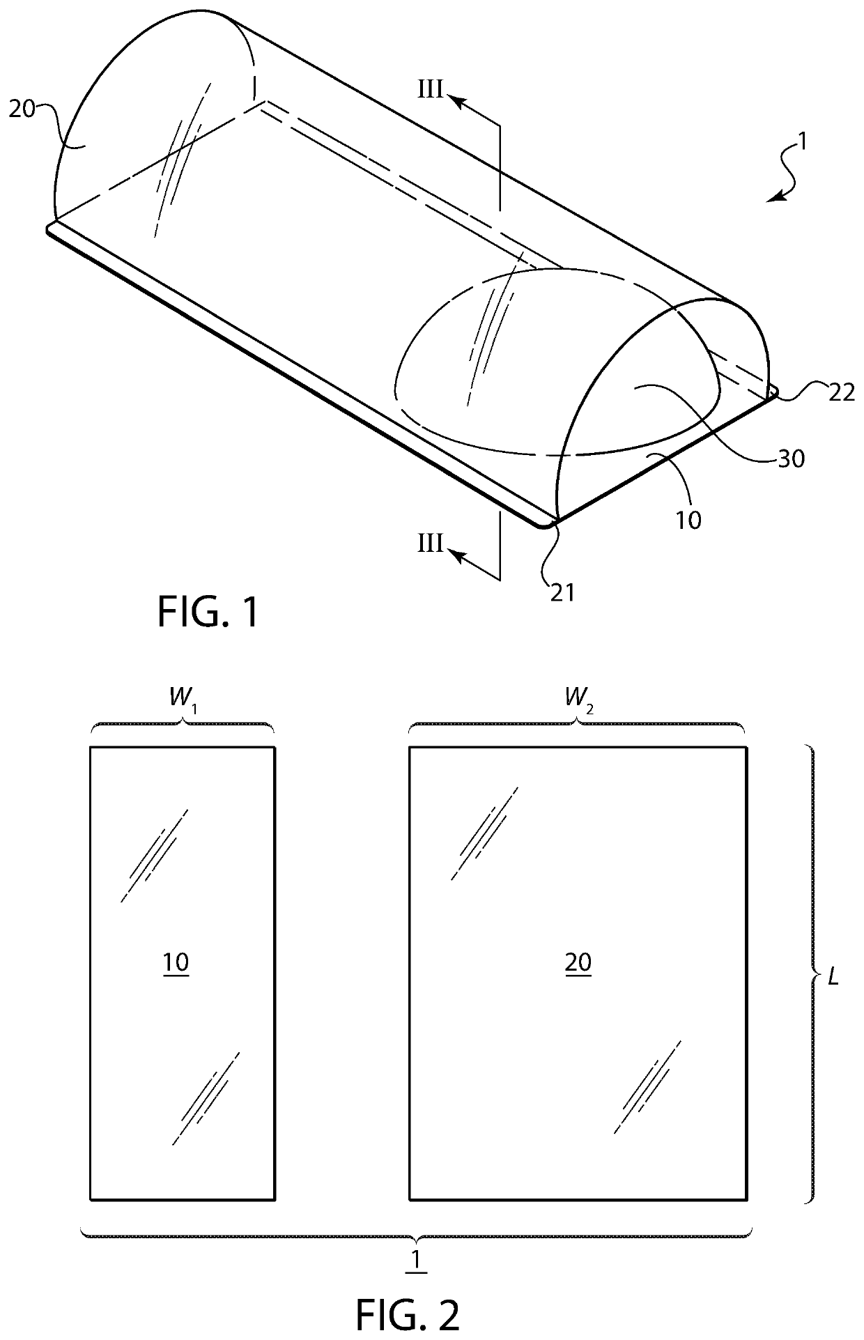
[0021]FIG. 1 shows the device 1 according to the invention. Device 1 is in the form of a sleeve having a flat bottom portion 10 and a rounded top portion 20, which is connected to bottom portion 10 via two seams 21, 22. An implant 30 can be placed inside the lumen of the device 1, as shown. As can be seen in FIG. 2, the bottom portion 10 is formed of a flat rectangle having the same length L as the top portion 10, but a smaller width W1 than the width W2 of top portion 20.

[0022]Device 1 is preferably constructed of a transparent film material that is pliable. Top portion 20 can be made of a different material than bottom portion 10. Top portion 20 is preferably made of a stretchable material. Bottom portion 10 can be made thicker and less pliable for enhanced stability. Top portion 20 is connected to bottom portion 10 via seams 21, 22, which can be formed by heat sealing or any other suitable method.

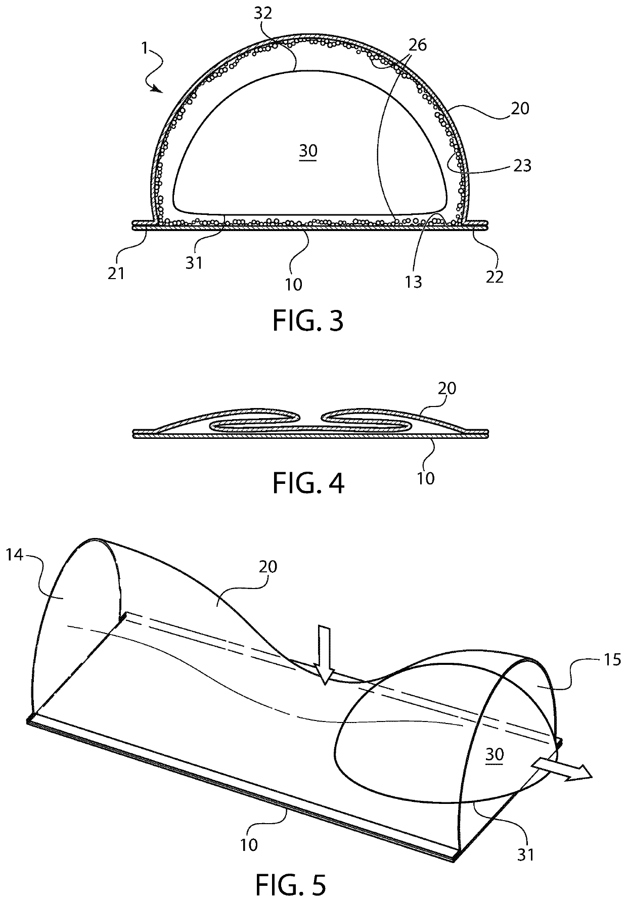
[0023]As shown in FIG. 3, an implant 30 can be placed inside device 1, so that the b...


PUM


Abstract

A device for inserting a pre-filled or silicone prosthesis into a surgical pocket is formed from a sleeve formed of a bottom layer and a top layer attached to the bottom layer along longitudinal edges of the bottom layer and top layer. The top layer has a greater width than the bottom layer so as to form a half-cylinder shape when the sleeve is filled. The sleeve has a constant cross-sectional area along a length of the sleeve. This device reduces the chances for the implant to rotate in an unintended manner due to the non-circular cross-section of the sleeve.

Description

CROSS-REFERENCE TO RELATED APPLICATIONS[0001]This application claims priority under 35 USC 119(e) of U.S. Provisional Application Ser. No. 62 / 942,795, filed on Dec. 3, 2019, the disclosure of which is herein incorporated by reference.BACKGROUND OF THE INVENTION1. Field of Invention[0002]This invention is a delivery apparatus which allows the placement of a pre-filled silicone breast prosthesis through a minimal access type of incision without damaging the shell of the implant by force or manipulation. This delivery apparatus prohibits the implant from turning while being placed into the pocket, ending upside down or in any other position that it was not intended to be placed, positioned or remain.2. The Prior Art[0003]Silicone implants have been available and in use for over 50 years. They are sold in a pre-filled condition. Their surgical placement without a device necessitates longer incisions, which lead to longer scars, which is not usually preferred by the patient or the surgeo...

Claims


Application Information

Patent Timeline
Patent Type & Authority Applications(United States)
IPC IPC(8): A61F2/12A61F2/00
CPCA61F2/12A61F2/0095A61F2210/0057A61F2220/0058A61F2240/001A61F2250/0018A61F2250/0091
Inventor BAKSHANDEH, NORMAN
Owner BAKSHANDEH NORMAN
Learn More