Fence mesh and machine for the formation thereof
a technology of knotted wire and wire mesh, which is applied in the direction of fencing wire, other domestic objects, wire articles, etc., can solve the problems of damage to the hides of livestock, and increasing the gap between the stay wires
- Summary
- Abstract
- Description
- Claims
- Application Information
AI Technical Summary
Benefits of technology
Problems solved by technology
Method used
Image
Examples
first embodiment
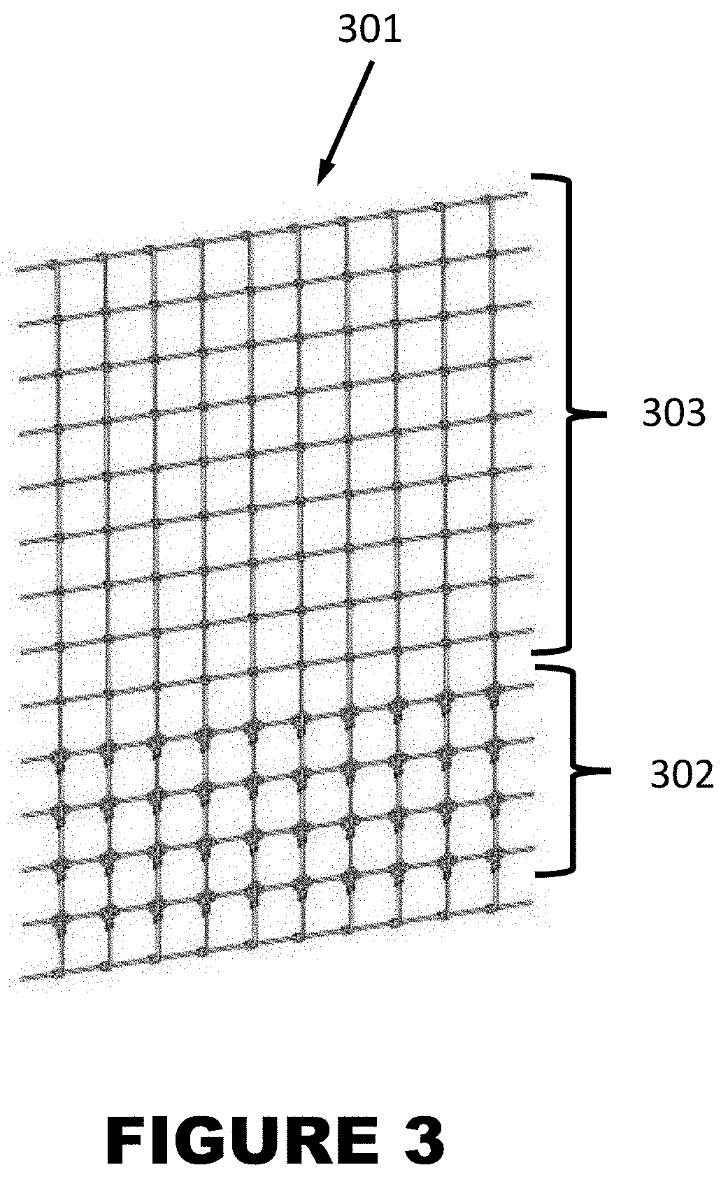
[0092]To produce the fence according to the present invention, machine 600 is configured to include a primary zone including at least one fixed knot box 801, and a secondary zone including at least one stay knot box 701. The same five drive shafts 608 pass through all of the fixed knot boxes 801 and stay knot boxes 701. Each drive shaft therefore provides the same rotary motion to all knot boxes at the same time. The first rotary motion received by each fixed knot box 801 is the same as the first rotary motion received by each stay knot box 701. The second rotary motion received by each fixed knot box 801 is the same as the second rotary motion received by each stay knot box 701. The third rotary motion received by each fixed knot box 801 is the same as the third rotary motion received by each stay knot box 701. The fourth rotary motion received by each fixed knot box 801 is the same as the fourth rotary motion received by each stay knot box 701. The fifth rotary motion received by ...
second embodiment
[0093]To produce the fence according to the present invention, machine 600 is configured to include a primary zone including at least one fixed knot box 801, a secondary zone including at least one stay knot box 701, and a tertiary zone including at least one fixed knot box 801. The same five drive shafts 608 pass through all of the fixed knot boxes 801 and stay knot boxes 701. Each drive shaft therefore provides the same rotary motion to all knot boxes at the same time. The first rotary motion received by each fixed knot box 801 is the same as the first Jo rotary motion received by each stay knot box 701. The second rotary motion received by each fixed knot box 801 is the same as the second rotary motion received by each stay knot box 701. The third rotary motion received by each fixed knot box 801 is the same as the third rotary motion received by each stay knot box 701. The fourth rotary motion received by each fixed knot box 801 is the same as the fourth rotary motion received b...
third embodiment
[0094]To produce the fence according to the present invention, machine 600 is configured to include a primary zone including at least one stay knot box 701, a secondary zone including at least one fixed knot box 801, and a tertiary zone including at least one stay knot box 701. The same five drive shafts 608 pass through all of the fixed knot boxes 801 and stay knot boxes 701. Each drive shaft therefore provides the same rotary motion to all knot boxes at the same time. The first rotary motion received by each fixed knot box 801 is the same as the first rotary motion received by each stay knot box 701. The second rotary motion received by each fixed knot box 801 is the same as the second rotary motion received by each stay knot box 701. The third rotary motion received by each fixed knot box 801 is the same as the third rotary motion received by each stay knot box 701. The fourth rotary motion received by each fixed knot box 801 is the same as the fourth rotary motion received by ea...
PUM
| Property | Measurement | Unit |
|---|---|---|
| Angle | aaaaa | aaaaa |
| Angle | aaaaa | aaaaa |
Abstract
Description
Claims
Application Information
 - R&D
- Intellectual Property
- Life Sciences
- Materials
- Tech Scout
- Unparalleled Data Quality
- Higher Quality Content
- 60% Fewer Hallucinations
Browse by: Latest US Patents, China's latest patents, Technical Efficacy Thesaurus, Application Domain, Technology Topic, Popular Technical Reports.
© 2025 PatSnap. All rights reserved.Legal|Privacy policy|Modern Slavery Act Transparency Statement|Sitemap|About US| Contact US: help@patsnap.com


