

Communication system and base station
a communication system and base station technology, applied in the field of communication systems, can solve problems such as collision risks in the transmission system, and achieve the effect of high-reliability communication systems
- Summary
- Abstract
- Description
- Claims
- Application Information
AI Technical Summary
Benefits of technology
Problems solved by technology
Method used
Image

Examples
first embodiment
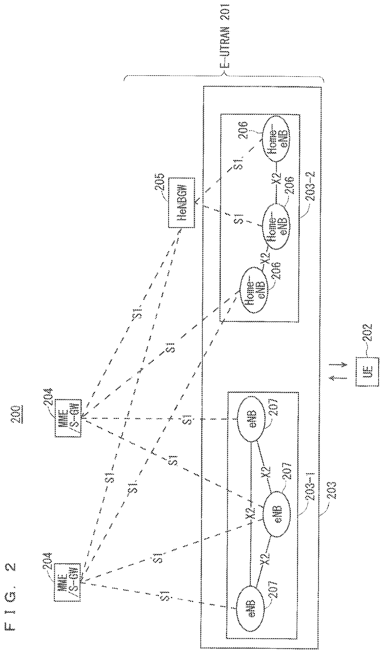
[0092]FIG. 2 is a block diagram showing an overall configuration of an LTE communication system 200 which is under discussion of 3GPP. FIG. 2 is described here. A radio access network is referred to as an evolved universal terrestrial radio access network (E-UTRAN) 201. A user equipment device (hereinafter, referred to as a “user equipment (UE)”) 202 that is a communication terminal device is capable of radio communication with a base station device (hereinafter, referred to as a “base station (E-UTRAN Node B: eNB)”) 203 and transmits and receives signals through radio communication.
[0093]Here, the “communication terminal device” covers not only a user equipment device such as a mobile phone terminal device, but also an unmovable device such as a sensor. In the following description, the “communication terminal device” may be simply referred to as a “communication terminal”.
[0094]The E-UTRAN is composed of one or a plurality of base stations 203, provided that a control protocol for...
second embodiment
[0238]As a notification method of the SCG failure information from the UE to the master base station using a bearer including a plurality of transmission paths in the radio interface from the UE for uplink C-Plane data transmission, i.e., a UL split SRB, the UE may initiate RRC connection re-establishment. Alternatively, the UE may autonomously change the transmission path of uplink split SRB1 from the SCG to the MCG. The above-mentioned notification method of the SCG failure information may be applied to a case where the use of the SCG is configured as the transmission path of UL split SRB1.
[0239]The above-mentioned transmission path change of the uplink split bearer may be applied to uplink split SRB2 and / or an uplink split DRB.
[0240]When the above-mentioned method is applied, the following problems occur. Specifically, the UE performs reconnection with the MCG as well as the SCG through RRC connection re-establishment, and thus time takes before the completion of RRC connection r...
third embodiment
[0268]In a beam failure recovery request (Beam Failure Recovery Request; hereinafter also referred to as a BFRQ in some cases) using the PUCCH, transmission may be performed using an SR PUCCH. As another example, a beam measurement result report PUCCH may be used. The base station may perform configuration of a BFRQ PUCCH to the UE. For the configuration, for example, RRC signaling may be used.
[0269]However, in the BFRQ using the PUCCH, details of RRC signaling used for configuration of the PUCCH are not disclosed, and a PUCCH format for transmitting the BFRQ is not disclosed. As a result, the UE cannot notify the base station of the BFRQ by using the PUCCH. Further, in the BFRQ PUCCH, how to secure reliability is not disclosed. As a result, reliability in the BFRQ notification from the UE to the base station cannot be secured.
[0270]Solutions to the above problems are disclosed below.
[0271]The UE transmits the BFRQ PUCCH by using a predetermined sequence. Application of the predeter...
PUM
 Abstract
Description
Claims
Application Information