Micro-movement and gesture detection using radar

a technology of gesture detection and micro-movement, applied in the field of micro-movement and gesture detection using radar, can solve problems such as negative medical outcomes, and achieve the effect of reducing the amount of detected micro-shivering

Pending Publication Date: 2021-06-10
HILL ROM SERVICES
View PDF12 Cites 4 Cited by
  • Summary
  • Abstract
  • Description
  • Claims
  • Application Information

AI Technical Summary

Benefits of technology

[0011]Another aspect relates to a method for mitigating micro-shivering, the method comprising: transmitting a radar signal transmission toward a target area; receiving reflected radar signals from the ta

Problems solved by technology

However, the inability to quickly detect micro-movements that are indicative of a physiological

Method used


Image

  • Micro-movement and gesture detection using radar
  • Micro-movement and gesture detection using radar
  • Micro-movement and gesture detection using radar

Examples


Embodiment Construction

[0020]This patent application is directed to using radar to detect movements. These movements can be categorized into (1) micro-movements that are indicative of a physiological condition such as micro-shivering, peristaltic intestinal motion, jugular vein distention, and pregnancy contractions; and (2) gestures for controlling one or more types of devices.

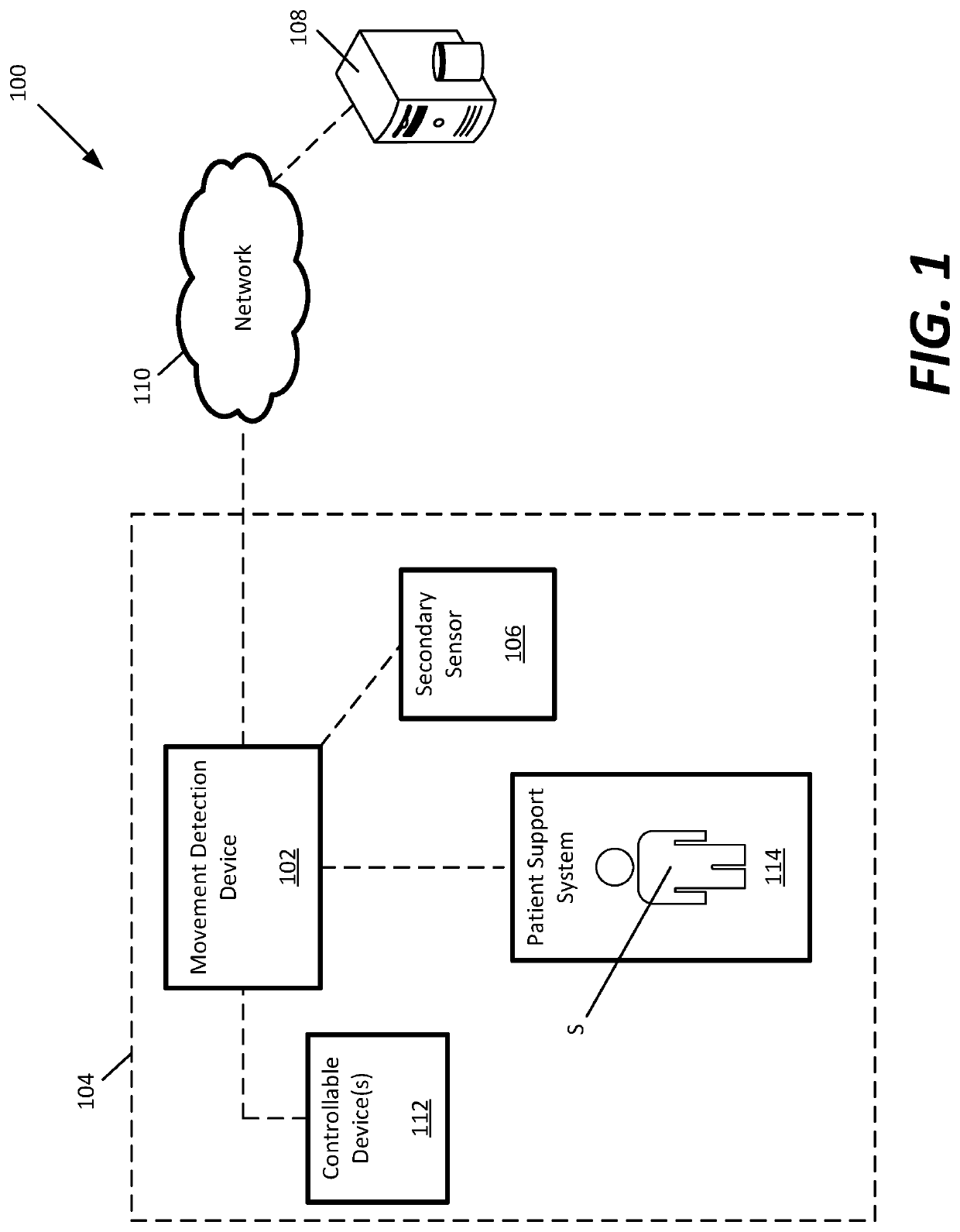
[0021]FIG. 1 schematically illustrates an example monitoring system 100. The monitoring system 100 includes a movement detection device 102 that detects micro-movements and gestures from a subject S located in a subject arrangement area 104. The movement detection device 102 detects these movements without touching or contacting the subject S.

[0022]In some examples, the movement detection device 102 is separately installed within the subject arrangement area 104. In other examples, the movement detection device 102 is incorporated into another device positioned within a close vicinity of the subject S such as a patient support syst...


PUM


Abstract

A movement detection device includes a signal transmission device configured to transmit a radar signal transmission toward a target area and to receive reflected radar signals, and a signal analysis device configured to analyze the reflected radar signals to detect a movement in the target area that is indicative of micro-shivering. In response to detecting the micro-shivering, the movement detection device generates an alarm.

Description

INTRODUCTION[0001]Small ranges of movement such as micro-movements can sometimes indicate a physiological condition of a patient. For example, micro-shivering, peristaltic intestinal motion, jugular vein distention, and pregnancy contractions produce micro-movements that are often not detectable by caregivers without the aid of medical devices that are in contact with the patient.[0002]Prompt medical treatment is important to reduce negative medical outcomes. However, the inability to quickly detect micro-movements that are indicative of a physiological condition delays the response time for treatment, which can lead to negative medical outcomes.[0003]Additionally, it is important to maintain a sterile environment within a healthcare facility. Infection risks can be minimized by eliminating the need to physically touch devices. Also, it is desirable to enable patients to control the devices in their rooms (e.g., bed, TV, temperature control, etc.) without having to locate and physic...

Claims


Application Information

Patent Timeline
IPC IPC(8): A61B5/05G01S7/41G01S13/88G08B25/00A61B5/00A61B5/11A61B5/02A61B5/01
CPCA61B5/05G08B7/06G01S13/886G08B25/00A61B5/4205A61B5/4255A61B5/1126A61B5/1101A61B5/1123A61B5/02007A61B5/4356A61B5/7246A61B5/1107A61B5/01A61B5/746A61B5/486A61B5/725G01S7/415A61B2505/07A61B5/1114A61B5/0507A61B5/6889A61B5/02055A61B5/4233A61B5/7225A61B5/4839A61B2562/06G06F3/017
Inventor BAKER, STEVEN D.BERGSTROM, JENNIFERDALBERT, HEINZ-HERMANNFISK, BRANDON P.FU, YONGJIHOOD, MICHAEL S.LACHENBRUCH, CHARLES A.LANE, JOHN A.MUDGE, KENZI L.O'NEAL, MATTHEWSAUSER, FRANK E.SEIM, DOUGLAS A.SHANNON, GREGORY J.
Owner HILL ROM SERVICES
Why Eureka
Try Eureka