
Pipe insulation system

a technology of pipe insulation and pipe body, which is applied in the direction of pipe protection, coatings, mechanical equipment, etc., can solve the problems of premature corrosion of pipes, increased water ingress, and negative impact, and achieve the effect of reducing water ingress

Active Publication Date: 2021-06-10
INTEGRITY PROD & SUPPLIES INC
View PDF0 Cites 2 Cited by
  • Summary
  • Abstract
  • Description
  • Claims
  • Application Information

AI Technical Summary

Benefits of technology

The invention provides a covering for a building that has vents to allow air to pass through and create airflow within the covering. The vents have louvers to prevent water from entering. This helps to keep the building cool and dry.

Problems solved by technology

This moisture can have a negative impact on the material used to insulate the pipes and can also result in premature corrosion of the pipes.
As a result, the insulation may have to be replaced more frequently to improve the insulation quality and pipes may have to be replaced more frequently as they corrode.

Method used


Image

  • Pipe insulation system
  • Pipe insulation system
  • Pipe insulation system

Examples


Embodiment Construction

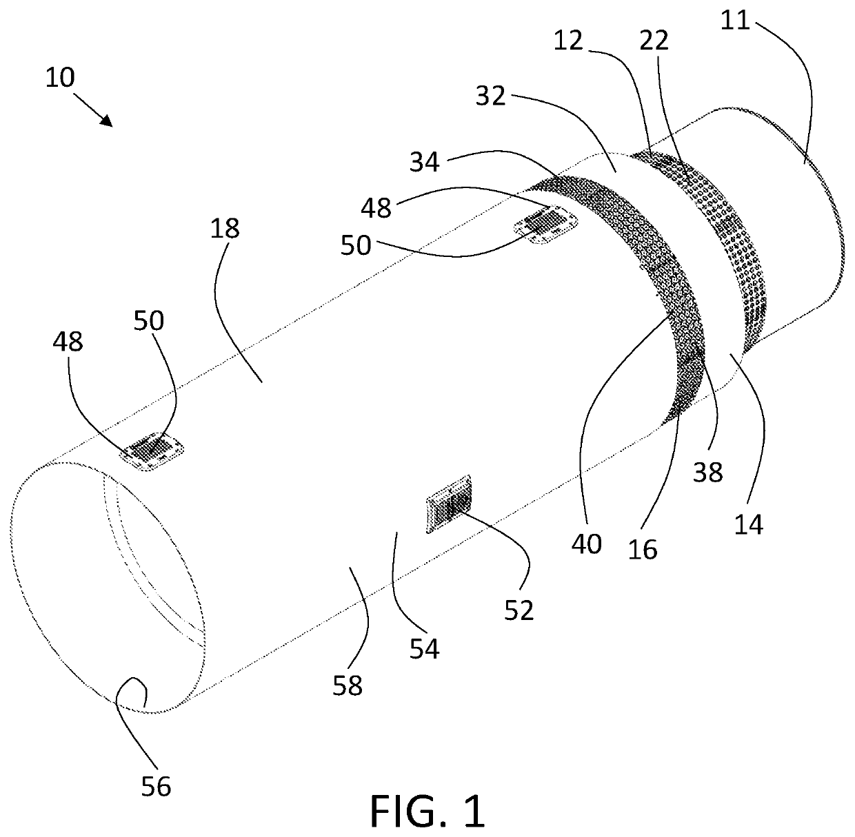
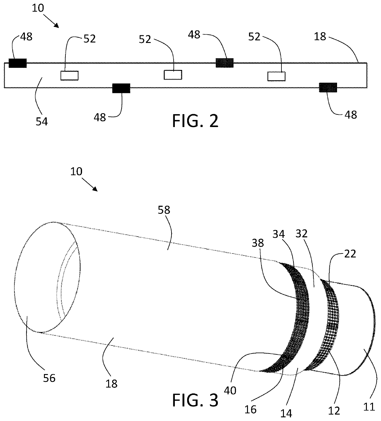
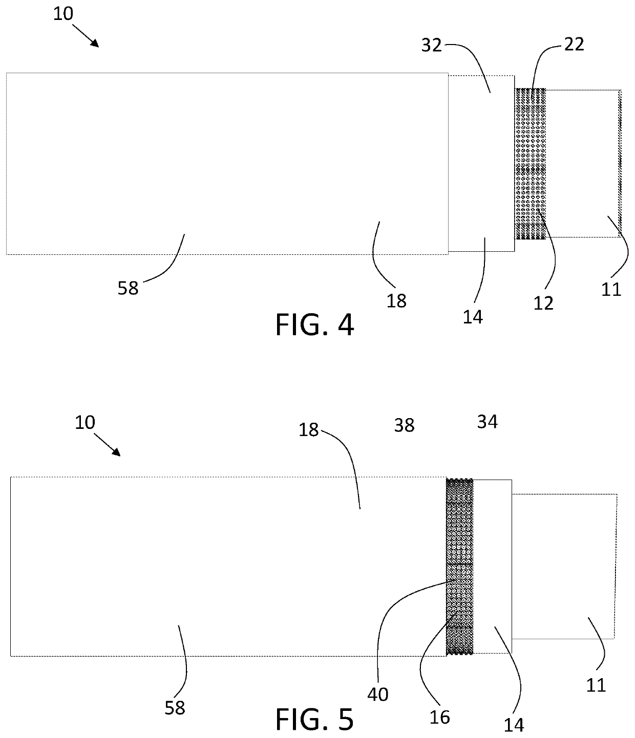
[0043]A pipe insulation system, generally identified by reference numeral 10, will now be described with reference to FIG. 1 through FIG. 23.

Spacer Wrap and Perforated Dimple Wrap:

[0044]Referring to FIG. 1, in the embodiment shown, pipe insulation system 10 has a spacer wrap 12, insulation material 14, a perforated dimple wrap 16 and cladding 18. Spacer wrap 12 has an upper surface 20 and a lower surface 22. Upper surface 20 has a plurality of convex protrusions 24. In the embodiment shown in FIG. 21, lower surface 22 has no protrusions or depressions. In the embodiment shown in FIG. 22, lower surface 22 has concave depressions 26 that correspond to convex protrusions 24. Upper surface 20 is positioned against a pipe 11 such that convex protrusions 24 make contact with pipe 11. By placing convex protrusions 24 against pipe 11, a unified and consistent air gap 28 is created between insulation material 14 and pipe 11. Air gap 28 helps to keep wet insulation material 14 off pipe 11, in...


PUM


Abstract

A pipe insulation system has a spacer wrap, an insulation material and a cladding. The spacer wrap has an upper surface and a lower surface. The upper surface of the spacer wrap has a plurality of convex protrusions. The upper surface is positioned against a pipe. The insulation material has an inner surface and an outer surface. The insulation material is positioned exterior to the lower surface of the spacer wrap. The cladding has an interior surface and an exterior surface. The cladding is positioned exterior to the outer surface of the insulation material.

Description

FIELD OF THE DISCLOSURE[0001]The present application relates generally to a pipe insulation system.BACKGROUND[0002]This section provides background information to facilitate a better understanding of the various aspects of the invention. It should be understood that the statements in this section of this document are to be read in this light, and not as admissions of prior art.[0003]When in operation, pipelines are exposed to moisture as a result of moisture intrusion from surroundings (rain, snow, chemical fumes, etc.) or sweating from dew point condensation. This moisture can have a negative impact on the material used to insulate the pipes and can also result in premature corrosion of the pipes. As a result, the insulation may have to be replaced more frequently to improve the insulation quality and pipes may have to be replaced more frequently as they corrode.BRIEF SUMMARY[0004]There is provided a pipe insulation system that has a spacer wrap, an insulation material and cladding...

Claims


Application Information

Patent Timeline
IPC IPC(8): F16L59/12F16L59/02F24F13/08
CPCF16L59/123F24F13/08F16L59/022F16L59/14F16L59/06F16L58/1063
Inventor BRIGHAM, GRAHAM
Owner INTEGRITY PROD & SUPPLIES INC
Learn More