Electrostatic atomizing device

Inactive Publication Date: 2010-12-30
PANASONIC CORP
View PDF13 Cites 7 Cited by
  • Summary
  • Abstract
  • Description
  • Claims
  • Application Information

AI Technical Summary

Benefits of technology

[0013]According to this embodiment, the reduced water is generated by dissolving the material forming at least one part of the discharge electrode in the water supplied to the discharge electrode or by dispersing in the form of the minute particle the material form

Problems solved by technology

Notably, objects (e.g. food products) can be deteriorated by not only action of a bacteria but also oxidization.
However, the mist of charged minute water particles generated f

Method used


Image

  • Electrostatic atomizing device
  • Electrostatic atomizing device
  • Electrostatic atomizing device

Examples


first embodiment

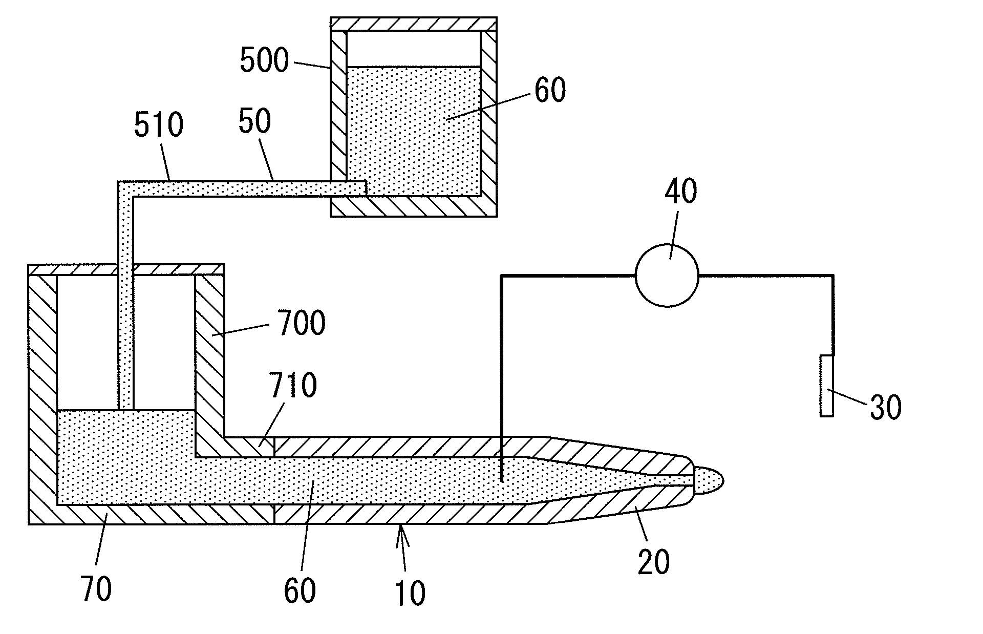
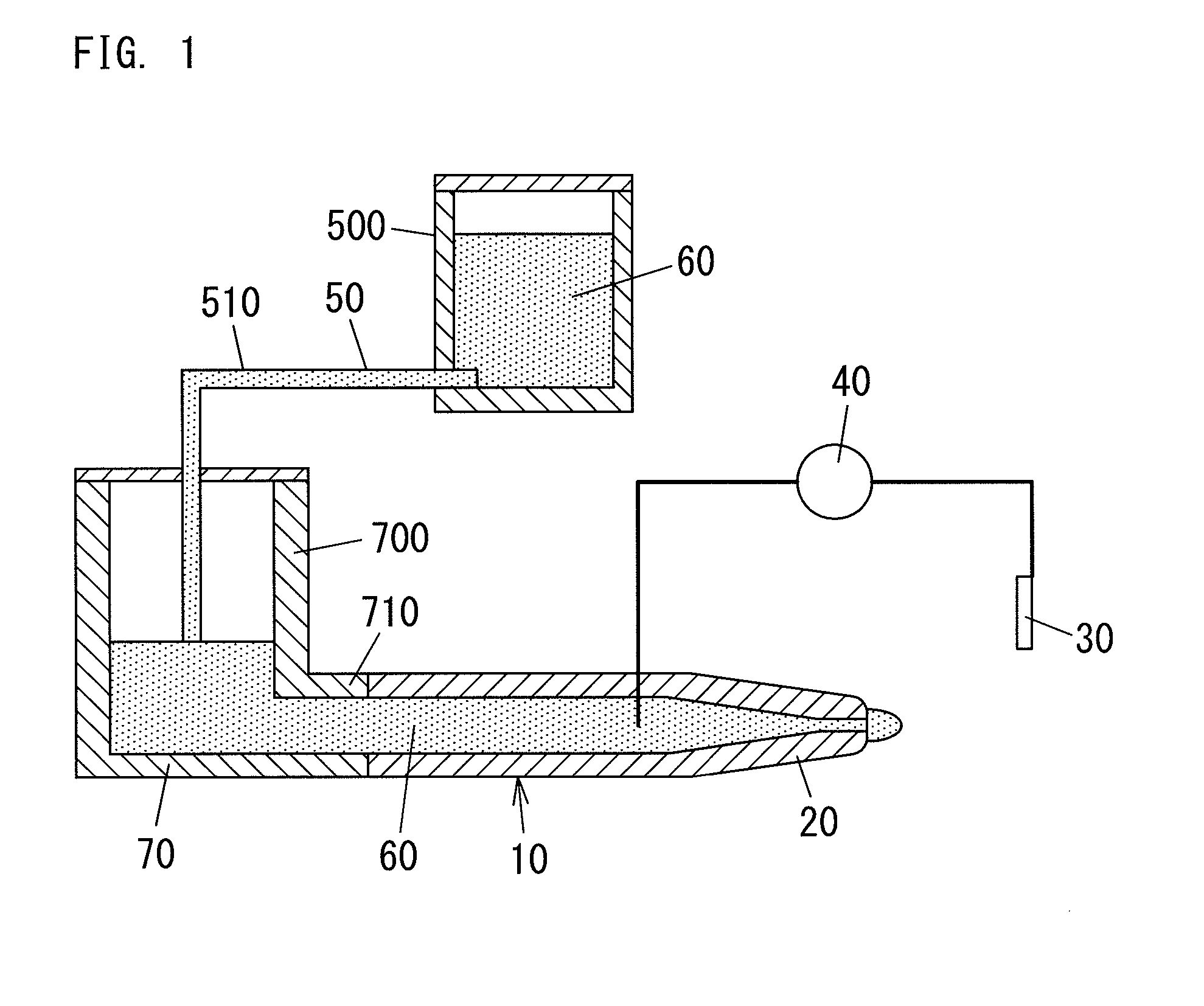
[0017]FIG. 1 shows an electrostatic atomizing device 10 which includes a discharge electrode (atomizing electrode) 20, an opposed electrode 30, and a voltage application device (voltage applying means) 40. The electrostatic atomizing device 10 further includes a reduced water provision device (reduced water providing means) 50 configured to have the discharge electrode 20 hold reduce water 60.

[0018]The discharge electrode 20 is made of metals and is shaped into a cylindrical shape (e.g. a circular cylindrical shape). The discharge electrode 20 has its front end portion (right end portion, in FIG. 1) which has its inner diameter made smaller towards its front end than at its rear end. The inner diameter at the front end of the discharge electrode 20 is selected such that the reduced water 60 outside the front end of the discharge electrode 20 can be kept in a spherical shape by its surface tension. In short, the reduced water 60 is prevented from flowing out from the front end of the...

second embodiment

[0039]As shown in FIG. 2, the electrostatic atomizing device 10A of the present embodiment includes the discharge electrode 20A, the opposed electrode 30A, the voltage application device 40, a housing 80, and a cooler 90. Since the voltage application device 40 is the same as that of the first embodiment 1, the voltage application device 40 is designated by the same reference number and no explanation is deemed necessary.

[0040]The discharge electrode 20A is shaped into a column shape, for example. The discharge electrode 20A has its outer diameter made smaller towards its front end than at its rear end. The discharge electrode 20A is made of the reducing material. For example, the reducing material can be selected from platinum (Pt), zinc (Zn), silver (Ag), and titanium (Ti).

[0041]The housing 80 is shaped into a box shape which having its entire first surface (upper surface, in FIG. 2) opened. The housing 80 is provided in its second surface (lower surface, in FIG. 2) with a communi...


PUM


Abstract

The electrostatic atomizing device includes a discharge electrode, an opposed electrode, and a voltage application device. The voltage application device is configured to apply a voltage between the discharge electrode and the opposed electrode so as to atomizing a liquid supplied to the discharge electrode. The electrostatic atomizing device further includes a reduced water provision device configured to supply reduced water as the above liquid to the discharge electrode.

Description

TECHNICAL FIELD[0001]The present invention is directed to an electrostatic atomizing device which generates a mist of charged minute water particles by causing an electrostatic atomizing phenomenon.BACKGROUND ART[0002]In the past, as disclosed in Japanese laid-open patent publication No. 2007-167796, there is known an electrostatic atomizing device configured to atomize water (e.g. tap water) to generate a mist of charged minute water particles of nanometer size.[0003]The aforementioned mist of charged minute water particles includes a radical such as a hydroxy radical. Such radical possesses an oxidation action. Therefore, the electrostatic atomizing device is capable of producing such as a deodorization effect, a virus and / or mold filtration effect, and a virus and / or mold suppression effect.[0004]For example, the above Japanese laid-open patent publication discloses the charged minute water particles is attached to and is percolated into a food product to make a sterilization, a ...

Claims


Application Information

Patent Timeline
IPC IPC(8): B05B5/00
CPCA61L9/14A61L2202/13A61L2202/15B05B5/057A61L2209/135B05B5/0255A61L2202/25
Inventor NAKADA, TAKAYUKIMIYATA, TAKAHIROSUDA, HIROSHIASANO, YUKIYASUMACHI, MASAHARU
Owner PANASONIC CORP
Why Eureka
Try Eureka