Bone-bonded artificial tooth structure

a bone-bonded, artificial tooth technology, applied in the field of artificial tooth structure, can solve the problems of inability to place the implant into the atrophied alveolar bone, complicated surgical procedures, and inability to perform type of alveolar bone reconstruction through bone augmentation, etc., to achieve good support strength and eliminate the long time needed for osseointegration. occurrence, the effect of good support strength

Inactive Publication Date: 2021-06-24
DENG YUN WEN
View PDF0 Cites 1 Cited by
  • Summary
  • Abstract
  • Description
  • Claims
  • Application Information

AI Technical Summary

Benefits of technology

The present invention provides an improved artificial tooth structure that can be fixed to a patient's alveolar bone to provide an immediate supporting strength sufficient for resisting a bite force when chewing food. This allows the patient to eat foods requiring cheking immediately after the tooth implant without needing to wait for the osseointegration of the alveolar bone with the implant. The invention also provides an improved artificial tooth structure that can be implanted to alveolar bones in various states of atrophies, can be applied to teeth at different oral locations and having different alveolar bone shapes, and can be used for patients having misaligned teeth or malocclusion. The artificial tooth structure is made using biocompatible biomedical materials and can be directly installed without the need of using other additional novel materials to meet specific using conditions. This makes the tooth implant efficient for dentists or oral surgeons.

Problems solved by technology

However, for a patient having a badly atrophied alveolar bone, i.e. with an almost completely resorbed alveolar bone and even a severely resorbed basal bone, it is impossible to place the implant into the atrophied alveolar bone.
However, this type of alveolar bone reconstruction through bone augmentation involves complicated surgical procedures and requires a relatively long time to complete, and could not be performed in the case of a special oral cavity condition that requires customized treatments.
Inaccurately placed implants would result in misaligned upper and lower jaws and tend to separate from the alveolar bone easily.
In the event the alveolar bone is not drilled with sufficient stability or the oral cavity vision in three-dimensional space is not well controlled, it is possibly to damage the facial nerve or cause bony crack of the alveolar bone.
Further, since the implant is made of a metal material that is obviously different from the alveolar bone tissue, these two components are not easily tightly bonded to each other.

Method used


Image

  • Bone-bonded artificial tooth structure
  • Bone-bonded artificial tooth structure
  • Bone-bonded artificial tooth structure

Examples


first embodiment

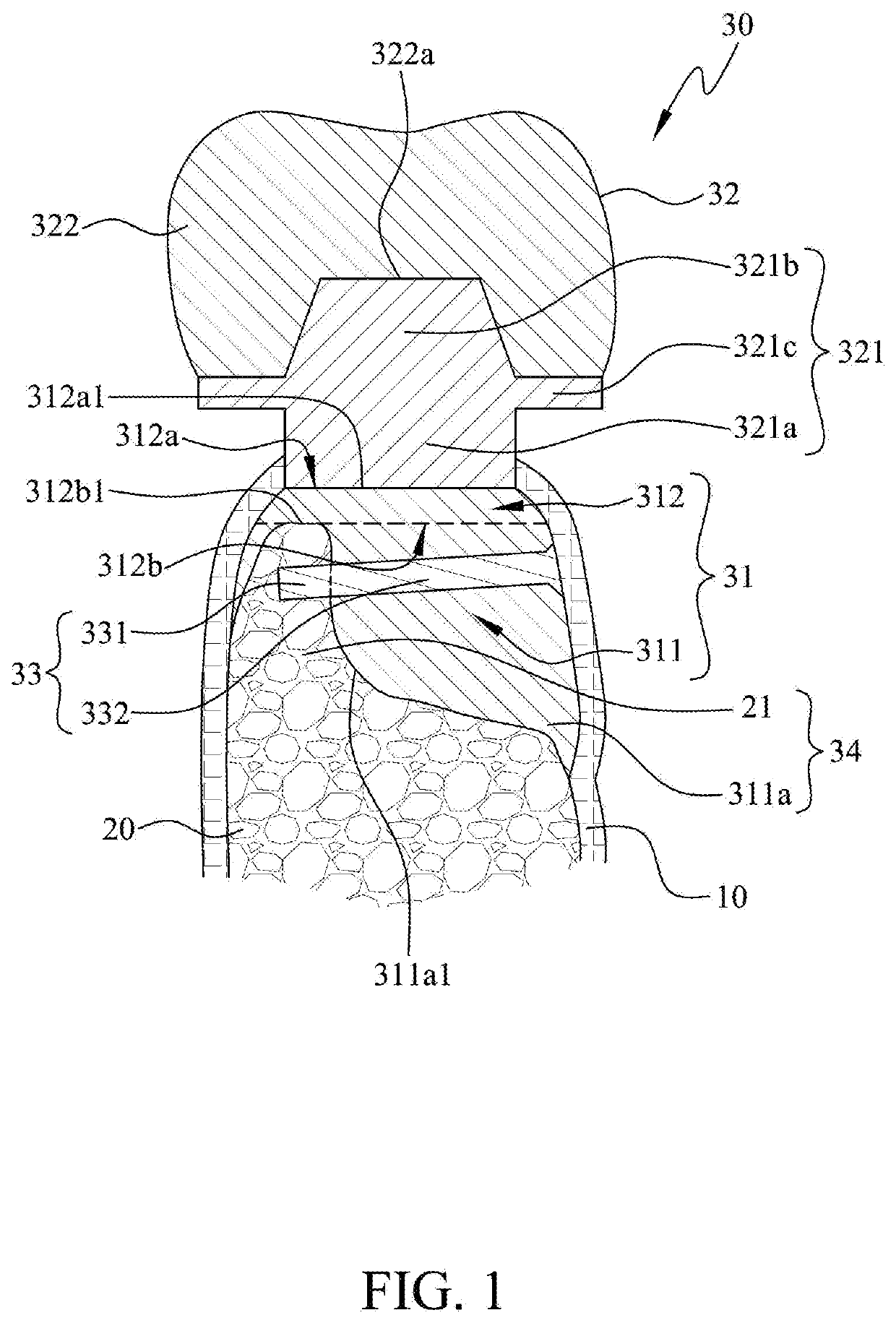
[0042]In the first embodiment as shown in FIG. 1, the bone-bonded artificial tooth structure 30 includes a base portion 31, a tooth portion 32 and a dental anchor 33. The base portion 31 is designed to be entirely fixed below the gum 10 and is divided into a lower connecting section 311 that located lower than a highest point of the narrowed bone top 21, and an upper connecting section 312 that located higher than the highest point of the narrowed bone top 21. The lower connecting section 311 is formed of a single independent connecting body 311a, which defines a 3D surface 311a1 completely corresponding to a configuration of a side wall surface of the narrowed bone top 21. The 3D surface 311a1 has one side in contact with the narrowed bone top 21, so that the narrowed bone top 21 and the lower connecting section 311 together form a locked part 34 that has an overall thickness larger than that of the narrowed bone top 21. More specifically, the 3D surface 311a1 of the lower connecti...

fourth embodiment

[0049]Please refer to FIG. 5 that shows the present invention configured for a patient having a missing tooth that is originally misaligned with other teeth. In this case, the abutment 321 can be changed in its shape to meet the patient's particular teeth condition. As shown in FIG. 5, the first end 321a of the abutment 321 is similarly formed as a bottom portion for contacting with the connecting surface 312a1, while the second end 321b of the abutment 321 is formed into a top portion slightly inclined relative to the first end 321a, such that the crown 322 of the tooth portion 32 mounted on the abutment 321 is also inclined in a direction to match the original teeth occlusion. Thus, the bone-bonded artificial tooth structure 30 according to the present invention can also be applied to misaligned original teeth.

fifth embodiment

[0050]Please refer to FIGS. 6A and 6B that show the present invention. In this embodiment, the base portion 31 is formed by 3D printing to have a substantially T-shaped independent connecting body 311a, which includes a vertical section 311a2 formed below the upper connecting section 312 and a horizontal section 311a3 formed at a lower end of the vertical section 311a2. As shown in FIG. 6B, when the first anchoring section 331 of the dental anchor 33 is inserted into the narrowed bone top 21 of the alveolar bone 20, the second anchoring section 332 of the dental anchor 33 is set outside of the independent connecting body 311a of the base portion 31 and located below the horizontal section 311a3 to abut against an underside of the horizontal section 311a3.

[0051]However, it is understood the description that the second anchoring section 332 of the dental anchor 33 is in contact with the underside of the horizontal section 311a3 is only illustrative to facilitate easy explanation of th...


PUM


Abstract

A bone-bonded artificial tooth structure for fixing to a patient's partially atrophied and gum covered alveolar bone includes a base portion having opposed lower and upper connecting sections located below and above a peak of the atrophied alveolar bone, respectively, the lower connecting section being in contact with the atrophied alveolar bone, and one side of the upper connecting section opposed to the atrophied alveolar bone defining a connecting surface; a tooth portion fixed to the connecting surface; and a dental anchor having an anchoring section inserted into the atrophied alveolar bone and another anchoring section inserted in the base portion to restrict the base portion from displacing relative to the alveolar bone. The bone-bonded artificial tooth structure fixed to the alveolar bone can immediately provide good supporting strength for chewing food without needing to wait for a long time for the osseointegration of the bone with the base portion.

Description

CROSS-REFERENCE TO RELATED APPLICATION[0001]This application claims the priority benefit of Taiwan application serial no. 108146775, filed on Dec. 19, 2019. The entirety of the above-mentioned patent application is hereby incorporated by reference herein and made a part of this specification.FIELD OF THE INVENTION[0002]The present invention relates to an artificial tooth structure that can be customized for different patients, and more particularly, to a bone-bonded artificial tooth structure that can be securely fixed to an atrophied alveolar bone.BACKGROUND OF THE INVENTION[0003]In the past, removable dentures or fixed dental crowns and gum were used to treat a patient's miss teeth, particularly when a large number of teeth are missing. Recently, with the introduction of the tooth implant techniques into the prosthodontic field, the patient with missing teeth now may choose to get single or multiple teeth implant or even a full-mouth dental implant.[0004]For a patient having a hea...

Claims


Application Information

Patent Timeline
Patent Type & Authority Applications(United States)
IPC IPC(8): A61C8/00A61C5/35
CPCA61C8/005A61C5/35A61C8/0037A61C8/0068A61C8/0009A61C8/0018A61C8/003A61C8/0031A61C8/0045A61C8/0075A61C8/0077A61C13/0003A61C5/77
Inventor DENG, YUN-WEN
Owner DENG YUN WEN
Why Eureka
Try Eureka