Rotation tool
- Summary
- Abstract
- Description
- Claims
- Application Information
AI Technical Summary
Benefits of technology
Problems solved by technology
Method used
Image
Examples
first embodiment
[0037]A first embodiment of the invention will be described in detail below with reference to FIGS. 1 to 5 and FIGS. 15 to 17.
Overall Configuration of Rotation Tool
[0038]The overall configuration of a rotation tool according to the present embodiment will be described below.
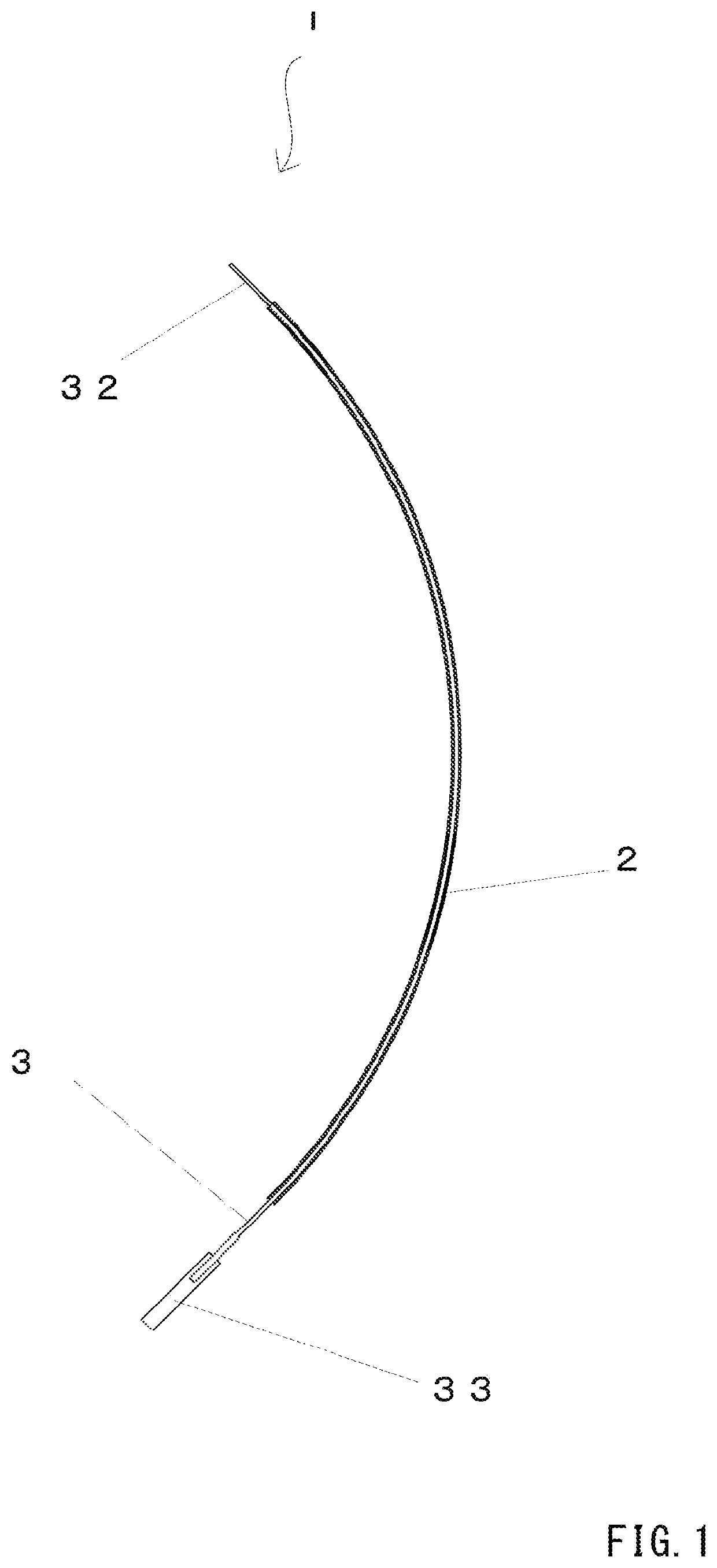
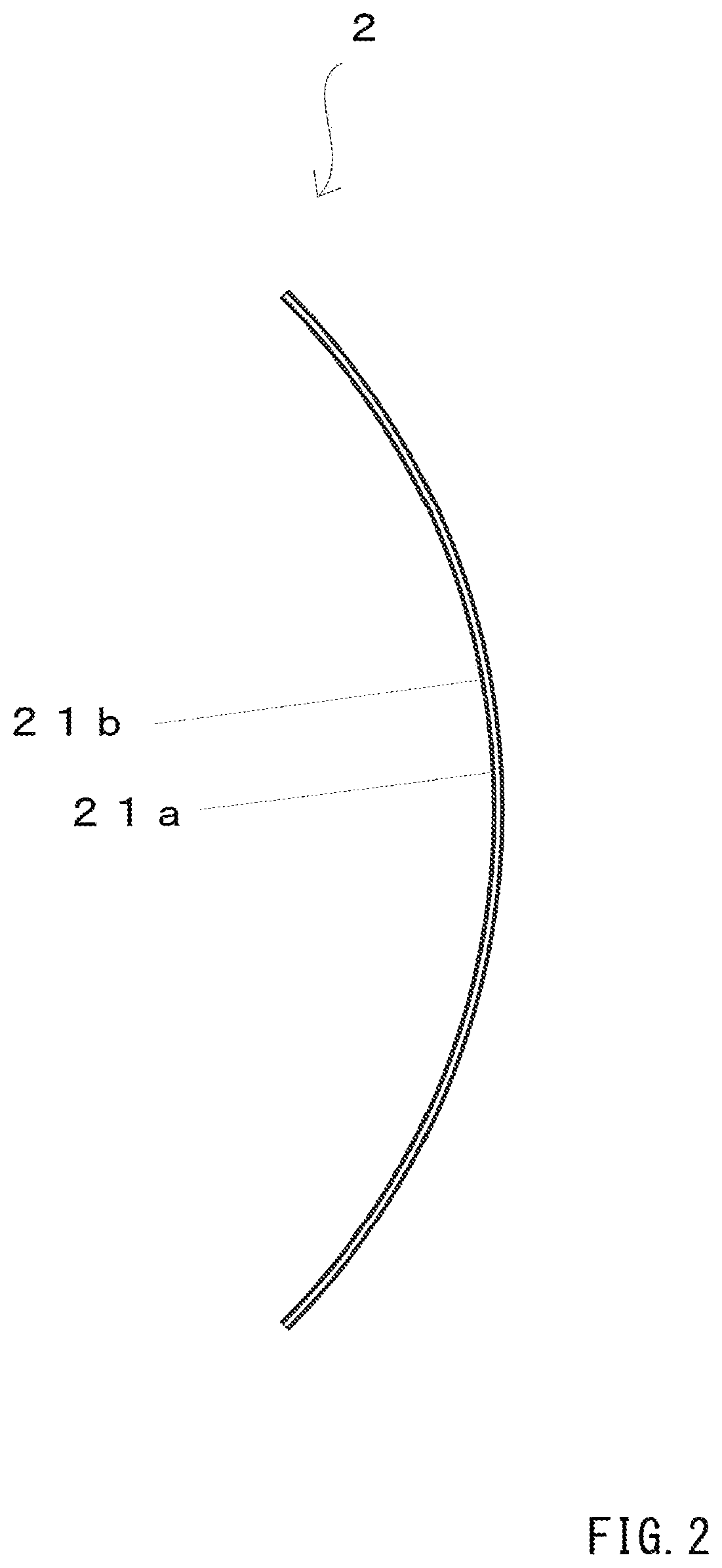
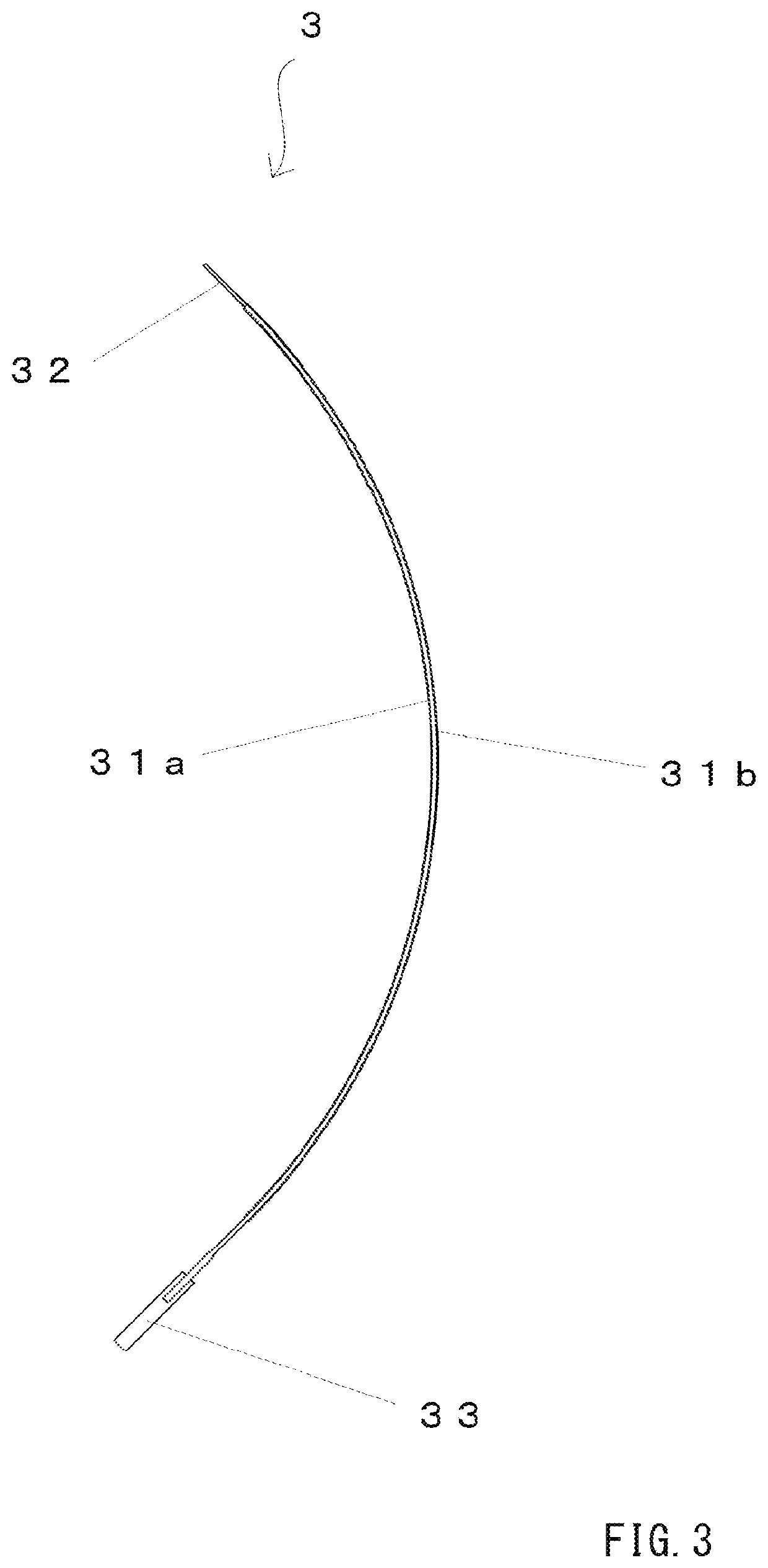
[0039]FIG. 1 shows a state of a rotation tool 1 according to the present embodiment in which an exterior body 2 and a shaft 3 are screwed to each other, and a tool portion 32 and a grip portion 33 protrude from the exterior body 2. In addition, FIG. 2 is a diagram showing the entire exterior body 2. In addition, FIG. 3 is a diagram showing the entire shaft provided with the tool portion 32 and the grip portion 33. In addition, FIGS. 4A and 4B are diagrams showing spiral grooves on a cylindrical inner surface of the exterior body 2. In addition, FIG. 5 is a diagram showing in detail a screwed state in which the exterior body 2 and the shaft 3 are screwed to each other.
[0040]As shown in FIGS. 1 to 3, the rotation t...
second embodiment
[0070]Next, a second embodiment of the invention will be described in detail with reference to FIGS. 6 to 11. The items common to the first embodiment may be omitted.
Overall Configuration of Rotation Tool
[0071]The overall configuration of a rotation tool 10 according to the present embodiment will be described below.
[0072]FIG. 6 shows a state of the rotation tool 10 according to the present embodiment in which an exterior body 20 and a shaft 30 are screwed to each other, and the tool portion 32, the grip portion 33, and a stopper member 37 protrude from the exterior body 20. In addition, FIGS. 7A and 7B are diagrams showing in detail a screwed state near the tool portion 32 and near the grip portion 33 when the exterior body 20 and the shaft 30 are screwed to each other,
[0073]As shown in FIG. 6, the rotation tool 10 includes the exterior body 20 and the shaft 30.
Exterior Body
[0074]The exterior body 20 has a cylindrical shape including a curved portion on at least a part thereof, and...
third embodiment
[0087]Next, a third embodiment according to the invention will be described in detail with reference to FIGS. 12 to 14A and 14B. The items common to the first and second embodiments may be omitted.
Overall Configuration of Rotation Tool
[0088]The overall configuration of a rotation tool 100 according to the present embodiment will be described below.
[0089]FIG. 12 shows a state of the rotation tool 100 according to the present embodiment in which the exterior body 2 and the shaft 3 are screwed to each other, the tool portion 32 and the grip portion 33 protrude from the exterior body 2, and a holding member 4 is attached to an outer circumference of the exterior body 2. In addition, FIG. 13 is a diagram showing only the holding member 4, and FIGS. 14A and 14B are diagrams showing details of a connection portion between the holding member 4 and the exterior body 2.
[0090]As shown in FIG. 12, the rotation tool 100 includes the exterior body 2, the shaft 3, and the holding member 4. Hereina...
PUM
| Property | Measurement | Unit |
|---|---|---|
| Length | aaaaa | aaaaa |
| Angle | aaaaa | aaaaa |
| Flexibility | aaaaa | aaaaa |
Abstract
Description
Claims
Application Information
 - R&D
- Intellectual Property
- Life Sciences
- Materials
- Tech Scout
- Unparalleled Data Quality
- Higher Quality Content
- 60% Fewer Hallucinations
Browse by: Latest US Patents, China's latest patents, Technical Efficacy Thesaurus, Application Domain, Technology Topic, Popular Technical Reports.
© 2025 PatSnap. All rights reserved.Legal|Privacy policy|Modern Slavery Act Transparency Statement|Sitemap|About US| Contact US: help@patsnap.com


