Blow-off device of air conditioner

a blow-off device and air conditioner technology, applied in vehicle heating/cooling devices, vehicle components, transportation and packaging, etc., can solve the problems of increased wind noise and increased passage, and achieve the effect of suppressing the influence of the pressure adjustment unit, suppressing the flow velocity, and suppressing wind nois

Active Publication Date: 2021-07-08
HONDA MOTOR CO LTD
View PDF0 Cites 0 Cited by
  • Summary
  • Abstract
  • Description
  • Claims
  • Application Information

AI Technical Summary

Benefits of technology

[0018]Here, in a state in which the air flows straight to the blow-off port along the intermediate part due to the wind direction variable means, it is possible to suppress the air from flowing to the upstream side inclined part. Therefore, by providing the inlet of the pressure adjustment unit on the upstream side inclined part, it is possible to prevent air from flowing into the inlet. As a result, in a state in which the air flows straight to the blow-off port along the intermediate part due to the wind direction variable means, the influence of the pressure adjustment unit can be suppressed.
[0019]According to the present invention, the blow-off device of the air conditioner is equipped with a pressure adjustment unit in the ventilation passage, and the inlet of the pressure adjustment unit is provided on an upstream side of a downstream side end portion at the time of maximum rotation of the wind direction variable means. As a result, it is possible to suppress the flow velocity in a place having the small cross-sectional area of the flow passage of the ventilation passage and to suppress wind noise.

Problems solved by technology

Along with this, a flow velocity in a place having a small cross-sectional area of the flow passage of the ventilation passage increases, and wind noise increases.

Method used


Image

  • Blow-off device of air conditioner
  • Blow-off device of air conditioner
  • Blow-off device of air conditioner

Examples


Embodiment Construction

[0026]Hereinafter, an embodiment of the blow-off device of the air conditioner according to the present invention will be described while referring to the attached drawings.

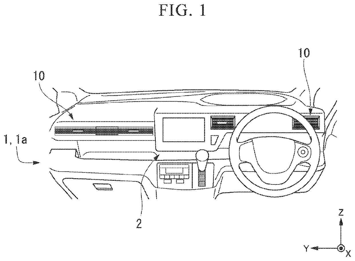
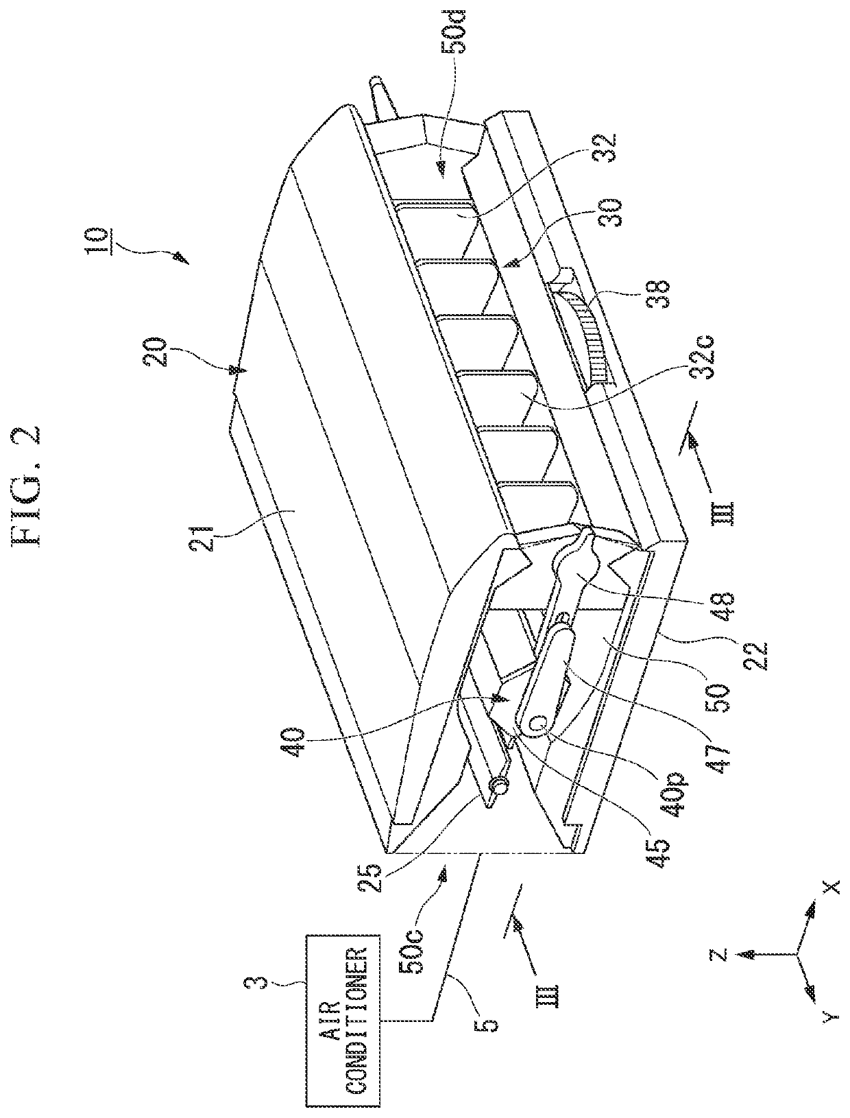
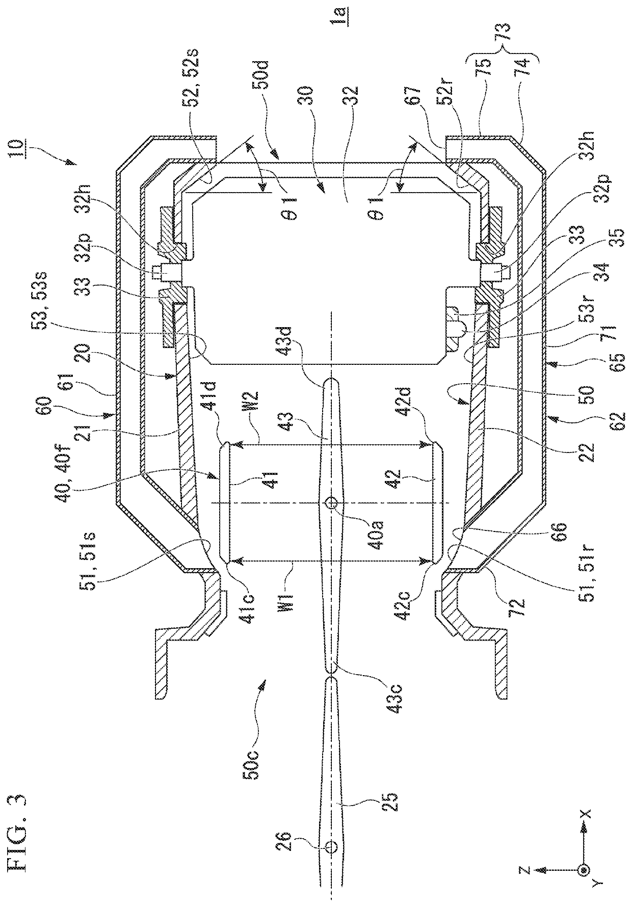
[0027]An X direction, a Y direction and a Z direction used in the following description are defined as follows. The X direction is an extending direction (a ventilation direction) of a ventilation passage formed inside the blow-off device. A+X direction is an opening direction of a blow-off port formed on a downstream side of the ventilation passage. The Y direction and the Z direction are directions orthogonal to each other and are each orthogonal to the X direction. As an example, when a cross-sectional shape of the ventilation passage orthogonal to the X direction is rectangular, a longitudinal direction is the Y direction and a transverse direction is a Z direction. To give an example in relation to a vehicle, the X direction is a front-rear direction of the vehicle, and the +X direction is a direction from t...


PUM


Abstract

A blow-off device (10) is equipped with a wind direction variable means (40) and a pressure adjustment unit (60) in a ventilation passage (50). The wind direction variable means is rotatably provided in the ventilation passage and can change a conditioned air from the inflow port (50c) toward a blow-off port (50d) and a second inclined part (52r) along an intermediate part (53r). The pressure adjustment unit prevents the pressure of the ventilation passage from exceeding a predetermined value by releasing the conditioned air to the outside of the ventilation passage. A bypass inlet (66) of the pressure adjustment unit is provided on an upstream side of an end portion (42d) in a +X direction at the time of maximum rotation of the wind direction variable means.

Description

CROSS-REFERENCE TO RELATED APPLICATION[0001]Priority is claimed on Japanese Patent Application No. 2020-000434, filed Jan. 6, 2020, the content of which is incorporated herein by reference.BACKGROUND OF THE INVENTIONField of the Invention[0002]The present invention relates to a blow-off device of an air conditioner.Description of Related Art[0003]A vehicle is equipped with an air conditioner. Conditioned air conditioned by the air conditioner is blown off from a blow-off device into a passenger compartment. The blow-off device is equipped with a wind direction variable means. The wind direction variable means is formed so that a wind direction can be changed, for example, in a vertical direction of a vehicle.[0004]In recent years, a blow-off device equipped with an inclined part in a case in addition to the wind direction variable means has been proposed (see, for example, Patent Document 1 (International Publication No. 2018 / 074022)). This blow-off device changes the wind direction...

Claims


Application Information

Patent Timeline
Patent Type & Authority Applications(United States)
IPC IPC(8): B60H1/34
CPCB60H1/345B60H1/3421B60H1/00514B60H1/00564B60H1/0065B60H2001/3471B60H1/3428
Inventor NAKASHIMA, YU
Owner HONDA MOTOR CO LTD
Why Eureka
Try Eureka