Supercharge Your Innovation With Domain-Expert AI Agents!

Aircraft wing comprising a mobile leading edge flap guided by a device located at the front of a wing box

a leading edge flap and wing box technology, applied in the field of aircraft wings, can solve the problems of limiting air resistance and unusability of the wing box volume swept by the rails, and achieve the effect of further functionalisation of the box and higher fuel amoun

Active Publication Date: 2021-07-08
SONACA
View PDF0 Cites 0 Cited by
  • Summary
  • Abstract
  • Description
  • Claims
  • Application Information

AI Technical Summary

Benefits of technology

The invention allows for a device that guides a mobile flap to be placed at the front of a wing without needing to pass through the front spar of the wing box. This means that the space within the wing box can be further utilized, for example to store more fuel.

Problems solved by technology

Furthermore, in a high speed cruising flight, the mobile flaps are retracted to limit the air resistance of the aircraft.
The penetrating nature of the guiding rails and driving rails makes the wing box volume swept by these rails unusable.

Method used


Image

  • Aircraft wing comprising a mobile leading edge flap guided by a device located at the front of a wing box
  • Aircraft wing comprising a mobile leading edge flap guided by a device located at the front of a wing box
  • Aircraft wing comprising a mobile leading edge flap guided by a device located at the front of a wing box

Examples


Embodiment Construction

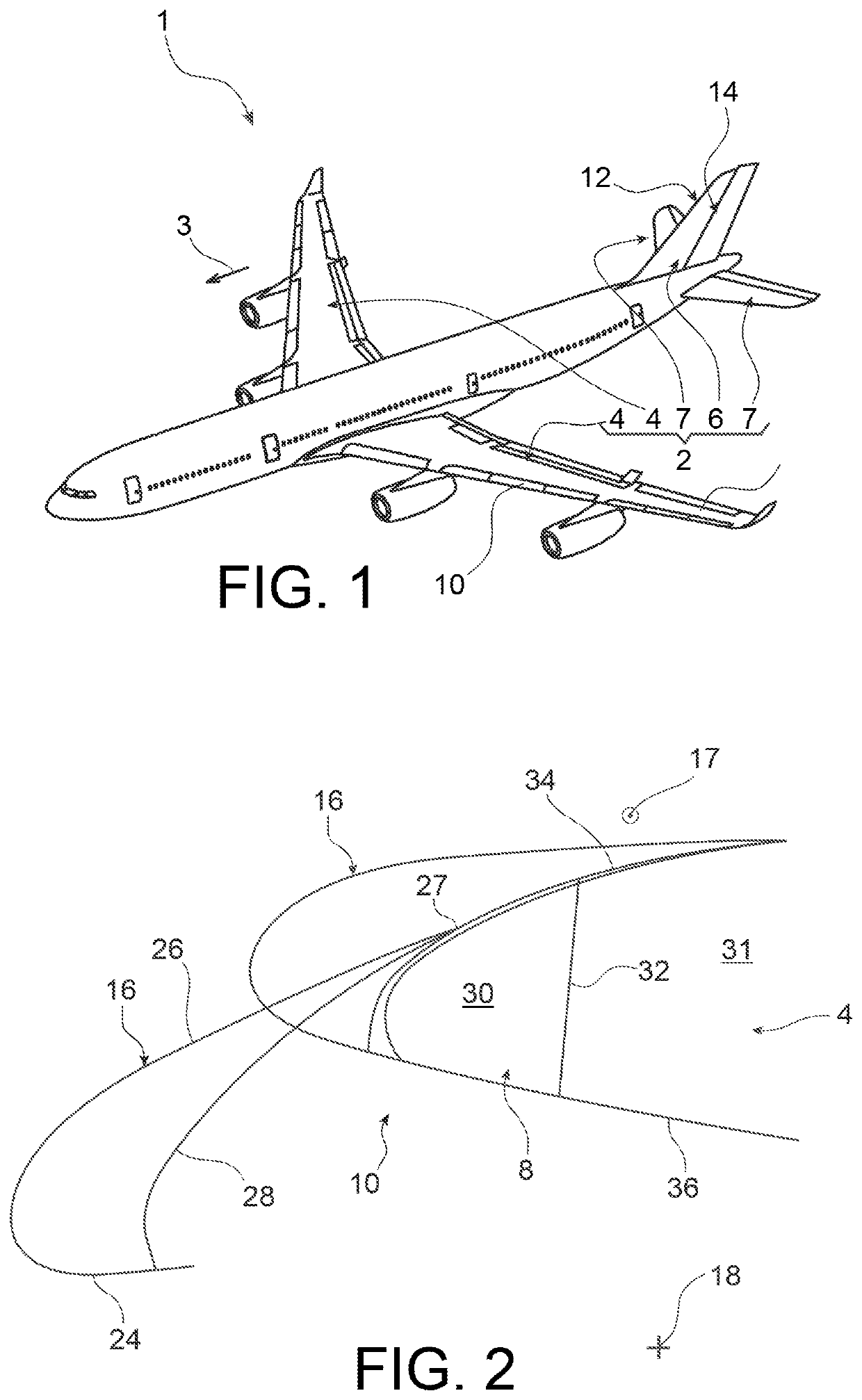
[0045]First with reference to FIG. 1, an aircraft 1 having an airfoil 2 consisting of a plurality of airfoil elements is represented.

[0046]Throughout the description that follows, the terms “front” and “rear” are to be considered with respect to a direction of advance of the aircraft experienced as a result of the thrust exerted by the aircraft engines, this direction being schematically represented by the arrow 3, and also called a “flight direction”.

[0047]Among the airfoil elements of the aircraft 1, there are provided two main wings, called the wings 4, a vertical stabiliser 6, as well as two horizontal tails 7 located at the rear of this aircraft.

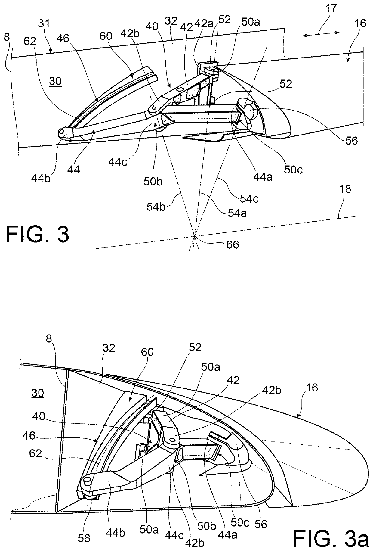
[0048]Regarding the wings 4, as discussed above, each of them comprise a wing fixed centre body 8, also called a main centre portion, this body being nearly the entire wing, and being located at the rear of a leading edge 10.

[0049]As is schematically shown in FIG. 2, it is the leading edge 10 of each of both wings 4 which can be fitted ...


PUM


Abstract

An aircraft wing including a mobile leading edge flap associated with a guiding device arranged at the front of a front spar of a wing box, and including: —a pivoting member having one end connected to the spar by an articulated linkage; —a pivoting member connected to one end of the member by an articulated linkage, the end of this member being connected to the flap via an articulated linkage; —a guide rail receiving a tracking member supported by the member, the rail defining a path inscribed on the surface of an imaginary sphere, the centre of which corresponds to a point of convergence of the axes of the three linkages.

Description

TECHNICAL FIELD[0001]The present invention relates to the field of aircraft wings, of the type comprising a wing fixed centre body carrying one or more mobile leading edge flaps, also called “Slats”.[0002]It is noted that the invention is applicable to any aircraft types, such as a flying wing, a fuselage tail-mounted engine airplane, a supersonic airplane, etc.State of Prior Art[0003]On aircrafts, each of both wings of the airfoil is generally fitted with high lift mobile flaps, mounted to the leading edge and to the trailing edge of the wing.[0004]In a known manner, the flaps are extended for landing and take-off phases in order to increase low or medium speed lift. Furthermore, in a high speed cruising flight, the mobile flaps are retracted to limit the air resistance of the aircraft. Still in a known manner to those skilled in the art, moving and guiding each flap are performed using means housed in a wing fixed centre body, as is clear for example in document EP 0 818 387. Thes...

Claims


Application Information

Patent Timeline
Patent Type & Authority Applications(United States)
IPC IPC(8): B64C9/22B64C9/02B64C3/18
CPCB64C9/22B64C3/185B64C9/02B64C3/50
Inventor GODFROID, XAVIER
Owner SONACA
Features
  • R&D
  • Intellectual Property
  • Life Sciences
  • Materials
  • Tech Scout
  • Unparalleled Data Quality
  • Higher Quality Content
  • 60% Fewer Hallucinations
Learn More