Work Machine
a work machine and work shaft technology, applied in mechanical machines/dredgers, fluid-pressure actuators, constructions, etc., can solve the problems of large moment of inertia of the swing structure including the work implement, flow rate loss, and additional load of the work machine, so as to achieve both energy efficiency and operability.
- Summary
- Abstract
- Description
- Claims
- Application Information
AI Technical Summary
Benefits of technology
Problems solved by technology
Method used
Image

Examples
first embodiment
[0023](1-1) Work Machine
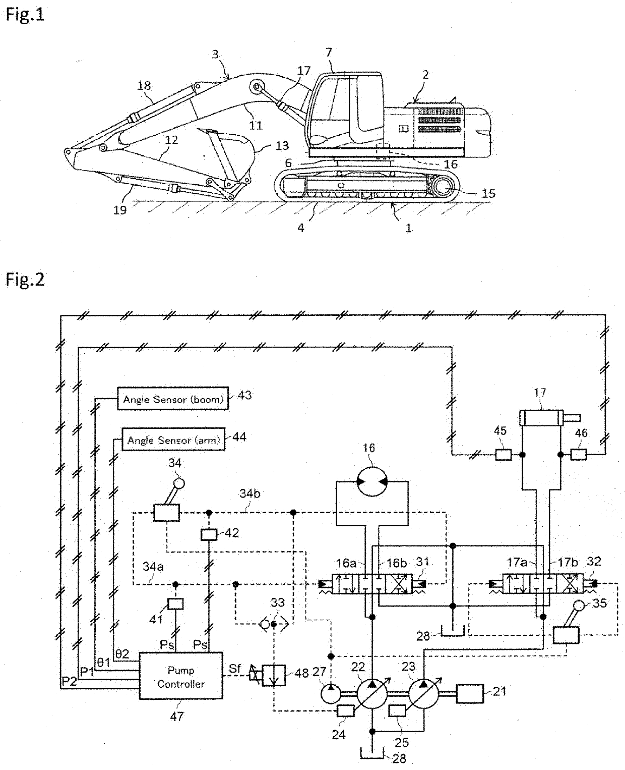
[0024]FIG. 1 is a perspective view of an appearance of a hydraulic excavator as an exemplary work machine according to each of embodiments of the present invention. Unless otherwise specified in the following, the direction forward of a driver's seat (the leftward direction in FIG. 1) is forward with respect to the machine. It should, however, be noted that the present invention can be applied to, not only the hydraulic excavator exemplified in the embodiments, but also other types of work machines, including a crane, provided with a swing structure that swings with respect to a base structure.
[0025]The hydraulic excavator shown in FIG. 1 includes a track structure 1, a swing structure 2 disposed on the track structure 1, and a work implement (front work implement) 3 mounted on the swing structure 2. The track structure 1 constitutes a base structure for the work machine and is a crawler type track structure traveling with left and right crawler belts 4. A st...
second embodiment
[0091](2-1) Configuration
[0092]FIG. 7 is a schematic diagram of a pump controller according to a second embodiment of the present invention. In FIG. 7, like parts are identified by like reference numerals used for the first embodiment. A command flow rate calculation section 56A of a pump controller 47A according to the present embodiment differs from the command flow rate calculation section 56 of the pump controller 47 in the first embodiment. Because this is the only difference in configuration of the present embodiment from the first embodiment, the following describes only the command flow rate calculation section 56A and omits describing other configurations.
[0093]Command Flow Rate Calculation Section
[0094]The command flow rate calculation section 56A in the present embodiment includes an operation time calculation section 66, a delay time calculation section 67, a target flow rate calculation section 68, and the minimum value selection section 65.
[0095]The operation time calc...
third embodiment
[0109](3-1) Configuration
[0110]FIG. 9 is a schematic diagram of a pump controller according to a third embodiment of the present invention. In FIG. 9, like parts are identified by like reference numerals used for the first and second embodiments. In the present embodiment, a flow rate rate-of-increase calculation section 55B and a command flow rate calculation section 56B of a pump controller 47B differ from the flow rate rate-of-increase calculation section 55 and the command flow rate calculation section 56 of the pump controller 47 in the first embodiment. Because this is the only difference in configuration of the present embodiment from the first embodiment, the following describes only the flow rate rate-of-increase calculation section 55B and the command flow rate calculation section 56B and omits describing other configurations.
[0111]Flow Rate Rate-of-Increase Calculation Section
[0112]The flow rate rate-of-increase calculation section 55B in the present embodiment differs fr...
PUM
 Abstract
Description
Claims
Application Information
 - R&D Engineer
- R&D Manager
- IP Professional
- Industry Leading Data Capabilities
- Powerful AI technology
- Patent DNA Extraction
Browse by: Latest US Patents, China's latest patents, Technical Efficacy Thesaurus, Application Domain, Technology Topic.
© 2024 PatSnap. All rights reserved.Legal|Privacy policy|Modern Slavery Act Transparency Statement|Sitemap